TRANSFER ASSEMBLY DISASSEMBLY

CAUTION / NOTICE / HINT
Note
Before installation of each part, thoroughly clean and dry it. Then apply grease or oil as necessary. Do not use alkaline chemicals to clean aluminum parts, rubber parts or precoated bolts. Also, do not use non-residue solvent or other cleaning oils to clean O-rings, oil seals or rubber parts.
PROCEDURE
-
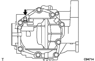
REMOVE TRANSFER AND TRANSAXLE SETTING STUD BOLT
-
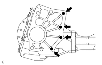
Remove the 4 transfer and transaxle setting stud bolts from the transfer case sub-assembly.
-
-
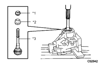
REMOVE NO. 2 TRANSFER CASE PLUG
-
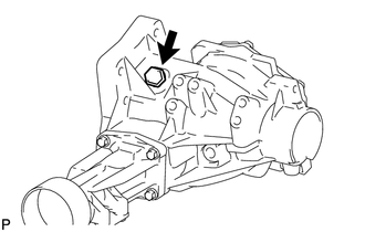
Remove the No. 2 transfer case plug from the transfer case sub-assembly.
-
Remove the gasket from the No. 2 transfer case plug.
-
-
REMOVE NO. 1 TRANSFER CASE PLUG
-
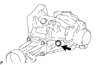
Remove the No. 1 transfer case plug from the transfer case sub-assembly.
-
Remove the gasket from the No. 1 transfer case plug.
-
-
REMOVE TRANSFER DRAIN PLUG
-
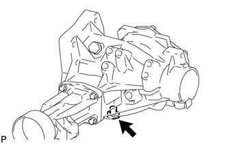
Remove the transfer drain plug from the transfer case sub-assembly.
-
Remove the gasket from the transfer drain plug.
-
-
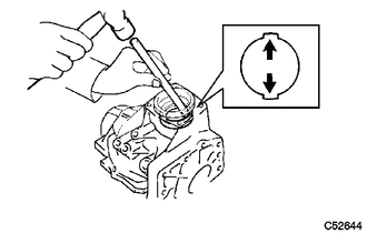
REMOVE TRANSFER CASE BREATHER PLUG
-
Using a chisel and hammer, lift the transfer case breather plug slightly.
-
Using a screwdriver, remove the transfer case breather plug from the transfer case cover sub-assembly.
-
-
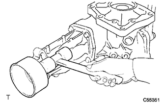
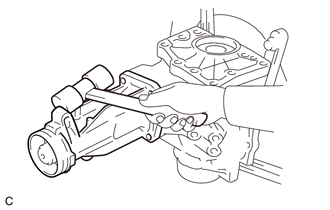
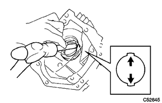
REMOVE TRANSFER CASE COVER SUB-ASSEMBLY
-
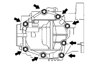
Remove the 8 bolts from the transfer case cover sub-assembly.
-
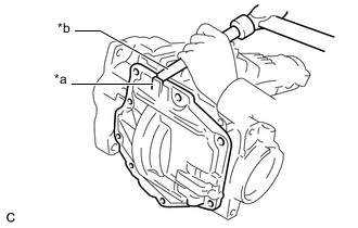
*a Rib *b Brass Bar Using a brass bar and a hammer, remove the transfer case cover sub-assembly from the transfer case sub-assembly.
Note
Place the brass bar on the rib protruding from the transfer case cover sub-assembly.
-
-
REMOVE BREATHER OIL DEFLECTOR
-
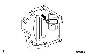
Remove the bolt and breather oil deflector from the transfer case cover sub-assembly.
-
-
REMOVE TRANSFER CASE STRAIGHT PIN
-
Remove the 4 transfer case straight pins from the transfer case sub-assembly.
-
-
SECURE TRANSFER ASSEMBLY
-
Attach the transfer assembly to the overhaul attachment.
-
-
REMOVE TRANSFER EXTENSION HOUSING DUST DEFLECTOR
-
Using a plastic hammer, remove the transfer extension housing dust deflector from the transfer extension housing sub-assembly.
-
-
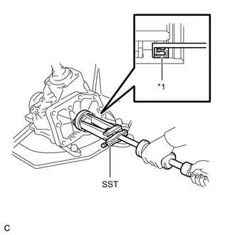
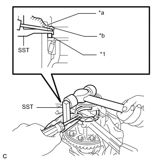
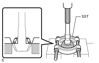
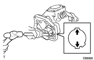
REMOVE TRANSFER EXTENSION HOUSING TYPE T OIL SEAL
-
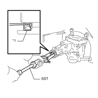
*1 Transfer Extension Housing Type T Oil Seal Using SST, remove the transfer extension housing type T oil seal from the transfer extension housing sub-assembly.
- SST
- 09308-00010
Note
Be careful not to damage the transfer extension housing type T oil seal contact surface or the inside surface of the transfer extension housing type T oil seal.
-
-
REMOVE TRANSFER EXTENSION HOUSING SUB-ASSEMBLY
-
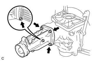
Remove the 4 bolts.
-
Using a plastic hammer, remove the transfer extension housing sub-assembly from the transfer case sub-assembly.
-
-
INSPECT PRELOAD
-
INSPECT RING GEAR BACKLASH
-
INSPECT TOOTH CONTACT BETWEEN RING GEAR AND DRIVEN PINION
-
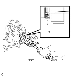
REMOVE TRANSFER CASE OIL SEAL
-
*1 Transfer Case Oil Seal Using SST, remove the transfer case oil seal from the transfer case sub-assembly.
- SST
- 09308-00010
Note
Do not damage the transfer case oil seal contact surface to the transfer case sub-assembly.
-
-
REMOVE TRANSFER CASE OIL SEAL RH
-
*1 Transfer Case Oil Seal RH Using SST, remove the transfer case oil seal RH from the transfer case sub-assembly.
- SST
- 09308-00010
Note
Do not damage the transfer case oil seal RH contact surface to the transfer case sub-assembly.
-
-
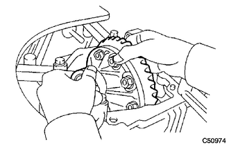
REMOVE BEARING CAP
-
Remove the 2 bolts and bearing cap from the transfer case sub-assembly.
-
-
REMOVE NO. 1 TRANSFER OUTPUT SHAFT SPACER
-
*1 No. 1 Transfer Output Shaft Spacer *a Screwdriver *b Piece of Cloth Using SST, a screwdriver and a hammer, remove the No. 1 transfer output shaft spacer from the transfer case sub-assembly.
- SST
- 09504-22012
Note
Do not damage the transfer case sub-assembly.
-
-
REMOVE NO. 2 TRANSFER RING GEAR MOUNTING CASE WASHER
-
Remove the No. 2 transfer ring gear mounting case washer from the transfer case sub-assembly.
-
-
REMOVE TRANSFER RING GEAR MOUNTING CASE
-
Remove the transfer ring gear mounting case from the transfer case sub-assembly.
-
-
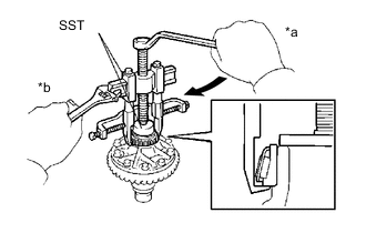
REMOVE DRIVEN PINION
-
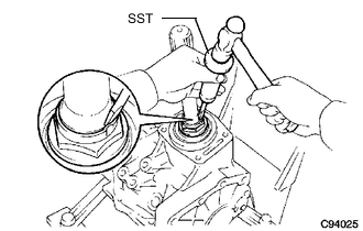
Using SST and a hammer, unstake the gear nut.
- SST
- 09930-00010
Tech Tips
-
Use SST with the flat side facing outward.
-
Do not machine the tip of SST with a grinder, etc.
-
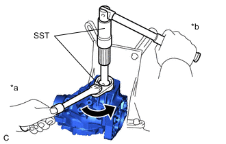
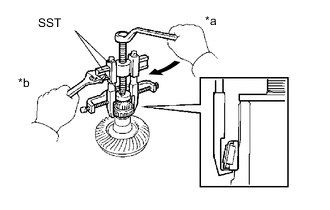
*a Turn *b Hold Using SST, remove the gear nut.
- SST
- 09326-20011
-
*1 Rear Transfer Driven Pinion Bearing (inner race) *2 Transfer Pinion Bearing Spacer *3 Driven Pinion Using a press, press out the driven pinion, rear transfer driven pinion bearing (inner race) and transfer pinion bearing spacer.
Note
-
Place a piece of cloth under the transfer case sub-assembly to prevent the driven pinion from dropping out of the rear transfer driven pinion bearing (inner race).
-
Use wooden blocks or similar objects under the transfer case sub-assembly to keep it level.
-
-
-
REMOVE FRONT TRANSFER DRIVEN PINION BEARING
-
Using SST and a press, remove the front transfer driven pinion bearing (inner race) from the driven pinion.
- SST
- 09950-00020
Note
-
Make sure to keep the outer race of the front transfer driven pinion bearing (inner race) from being applied force as shown the illustration.
-
Do not deform the cage of the front transfer driven pinion bearing (inner race) (when reusing the front transfer driven pinion bearing (inner race)).
-
Using a brass bar and a hammer, tap the 2 positions shown in the illustration on the front transfer driven pinion bearing (outer race) to remove it from the transfer case sub-assembly.
Note
Fit the brass bar to the 2 cutouts of the transfer case sub-assembly.
-
-
REMOVE TRANSFER OUTPUT SHAFT WASHER
-
Remove the transfer output shaft washer from the transfer case sub-assembly.
Note
If the transfer output shaft washer is damaged or deformed, replace it with a new one.
-
-
REMOVE RING GEAR MOUNTING CASE BEARING
-
for RH side:
-
Remove the ring gear mounting case bearing (outer race) from the transfer ring gear mounting case.
-
*a Turn *b Hold Using SST, remove the ring gear mounting case bearing (inner race) from the transfer ring gear mounting case.
- SST
- 09950-40011 ( 09951-04010, 09952-04010, 09953-04020, 09954-04010, 09955-04061, 09957-04010, 09958-04011 )
- 09950-60010 ( 09951-00440 )
Note
-
Use SST (09953-04020) after applying grease to its threads and tip.
-
Do not deform the cage of the ring gear mounting case bearing (inner race) (when reusing the ring gear mounting case bearing (inner race)).
-
Place identification marks on the left and right ring gear mounting case bearings to distinguish them (backside, teeth side). Then store them separately (when reusing the ring gear mounting case bearings).
-
-
for LH side:
-
*a Turn *b Hold Using SST, remove the ring gear mounting case bearing (inner race) from the transfer ring gear mounting case.
- SST
- 09950-40011 ( 09951-04010, 09952-04010, 09953-04020, 09954-04010, 09955-04061, 09957-04010, 09958-04011 )
- 09950-60010 ( 09951-00400 )
Note
-
Use SST (09953-04020) after applying grease to its threads and tip.
-
Do not deform the cage of the ring gear mounting case bearing (inner race) (when reusing the ring gear mounting case bearing (inner race)).
-
Place identification marks on the left and right ring gear mounting case bearings to distinguish them (backside, teeth side). Then store them separately (when reusing the ring gear mounting case bearings).
-
Using a brass bar and a hammer, tap the 2 positions shown in the illustration on the ring gear mounting case bearing (outer race) to remove it from the transfer case sub-assembly.
Note
Fit the brass bar to the 2 cutouts of the transfer case sub-assembly.
-
Remove the ring gear mounting case plate washer from the transfer case sub-assembly.
Note
If the ring gear mounting case plate washer is damaged or deformed, replace it with a new one.
-
-
-
INSPECT RUNOUT OF RING GEAR
-
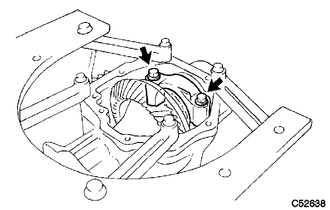
REMOVE RING GEAR
-
Secure the transfer ring gear mounting case in a vise using aluminum plates.
Note
Be careful not to damage the transfer ring gear mounting case in the vise.
-
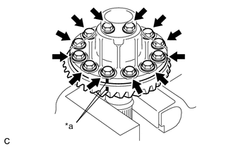
*a Matchmark Put matchmarks on the transfer ring gear mounting case and ring gear.
-
Remove the 12 bolts.
-
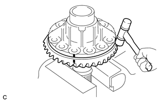
Using a plastic hammer, remove the ring gear from the transfer ring gear mounting case.
Note
Do not damage the ring gear teeth.
-
-
INSPECT TRANSFER RING GEAR MOUNTING CASE
-
REMOVE REAR TRANSFER DRIVEN PINION BEARING (OUTER RACE)
-
Using a brass bar and a hammer, tap the 2 positions shown in the illustration on the rear transfer driven pinion bearing (outer race) to remove it from the transfer case sub-assembly.
Note
Fit the brass bar to the 2 cutouts of the transfer case sub-assembly.
-