LANE DEPARTURE ALERT SYSTEM Main Switch Circuit
DESCRIPTION
The lane departure warning camera receives a lane-keeping assist main switch signal from the lane-keeping assist main switch.
WIRING DIAGRAM
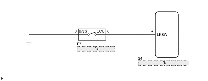
| *a | Lane-keeping Assist Main Switch |
| *b | Lane Departure Warning Camera |
PROCEDURE
-
INSPECT LANE-KEEPING ASSIST MAIN SWITCH
-
Remove the lane-keeping assist main switch.
-
Inspect the lane-keeping assist main switch.
Result Proceed to OK NG
NG 
REPLACE LANE-KEEPING ASSIST MAIN SWITCH Click here
OK 
-
-
CHECK HARNESS AND CONNECTOR (LANE-KEEPING ASSIST MAIN SWITCH - LANE DEPARTURE WARNING CAMERA AND BODY GROUND)
-
Disconnect the S4 lane departure warning camera connector.
-
Disconnect the F7 lane-keeping assist main switch connector.
-
Measure the resistance according to the value(s) in the table below.
Standard Resistance Tester Connection Condition Specified Condition S4-4 (LKSW) - F7-6 (ECU) Always Below 1 Ω F7-3 (GND) - Body ground Always Below 1 Ω S4-4 (LKSW) or F7-6 (ECU) - Body ground Always 10 kΩ or higher Result Proceed to OK NG
OK
PROCEED TO NEXT SUSPECTED AREA SHOWN IN PROBLEM SYMPTOMS TABLE Click here
NG
REPAIR OR REPLACE HARNESS OR CONNECTOR (LANE-KEEPING ASSIST MAIN SWITCH - LANE DEPARTURE WARNING CAMERA AND BODY GROUND)
-