DYNAMIC TORQUE CONTROL 4WD/AWD SYSTEM TC and CG Terminal Circuit
DESCRIPTION
Connecting terminals TC and CG of the DLC3 causes the 4WD ECU assembly to display a DTC on the multi-information display.
Tech Tips
When each warning light remains blinking, a short to ground in the wiring of terminal TC of the DLC3 or an internal short to ground in each ECU is suspected.
WIRING DIAGRAM
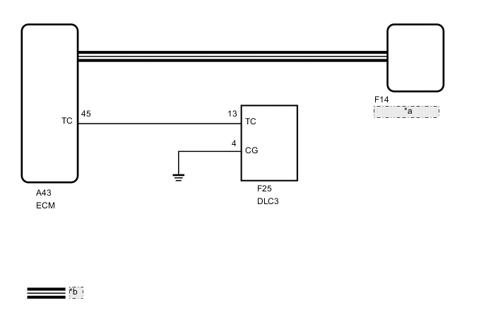
| *a | 4WD ECU Assembly |
| *b | CAN Communication Line |
CAUTION / NOTICE / HINT
PROCEDURE
-
CHECK FOR DTC (CAN COMMUNICATION SYSTEM)
-
Check if CAN communication system DTCs are output.
Result Result Proceed to CAN communication system DTCs are not output A CAN communication system DTCs are output B
B 
GO TO CAN COMMUNICATION SYSTEM (HOW TO PROCEED WITH TROUBLESHOOTING) Click here
A 
-
-
INSPECT DLC3
-
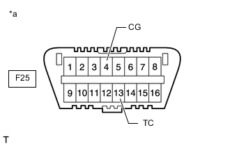
*a Front view of DLC3 Turn the ignition switch to ON.
-
Measure the voltage according to the value(s) in the table below.
Standard Voltage Tester Connection Condition Specified Condition F25-13 (TC) - F25-4 (CG) Ignition switch ON 11 to 14 V Result Proceed to OK NG
NG 
CHECK HARNESS AND CONNECTOR (TC OF DLC3 - TC OF ECM AND BODY GROUND) Click here
OK
-
-
REPLACE ECM
-
*a Front view of DLC3 Replace the ECM.
-
Using SST, connect terminals 13 (TC) and 4 (CG) of the DLC3.
- SST
- 09843-18040
-
Turn the ignition switch to ON.
-
Check that the "DIAGNOSIS CODE AWD FF" or "DIAGNOSIS CODE AWD XX (DTC)" is displayed.
Result Result Proceed to "DIAGNOSIS CODE AWD FF" or "DIAGNOSIS CODE AWD XX (DTC)" is displayed A "DIAGNOSIS CODE AWD FF" and "DIAGNOSIS CODE XX (DTC)" are not displayed B
A
END
B
REPLACE 4WD ECU ASSEMBLY Click here
-
-
CHECK HARNESS AND CONNECTOR (TC OF DLC3 - TC OF ECM AND BODY GROUND)
-
Turn the ignition switch off.
-
Disconnect the A43 ECM connector.
-
Measure the resistance according to the value(s) in the table below.
Standard Resistance Tester Connection Condition Specified Condition F25-13 (TC) - A43-45 (TC) Always Below 1 Ω F25-13 (TC) - Body ground Always 10 kΩ or higher Result Proceed to OK NG
NG
REPAIR OR REPLACE HARNESS OR CONNECTOR
OK
-
-
CHECK HARNESS AND CONNECTOR (CG OF DLC3 - BODY GROUND)
-
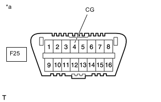
*a Front view of DLC3 Measure the resistance according to the value(s) in the table below.
Standard Resistance Tester Connection Condition Specified Condition F25-4 (CG) - Body ground Always Below 1 Ω Result Proceed to OK NG
NG
REPAIR OR REPLACE HARNESS OR CONNECTOR
OK
-
-
REPLACE ECM
-
*a Front view of DLC3 Replace the ECM.
-
Using SST, connect terminals 13 (TC) and 4 (CG) of the DLC3.
- SST
- 09843-18040
-
Turn the ignition switch to ON.
-
Check that the "DIAGNOSIS CODE AWD FF" or "DIAGNOSIS CODE AWD XX (DTC)" is displayed.
Result Result Proceed to "DIAGNOSIS CODE AWD FF" or "DIAGNOSIS CODE AWD XX (DTC)" is displayed A "DIAGNOSIS CODE AWD FF" and "DIAGNOSIS CODE XX (DTC)" are not displayed B
A
END
B
REPLACE 4WD ECU ASSEMBLY Click here
-