AUTOMATIC TRANSAXLE ASSEMBLY(When Using the Engine Support Bridge) REMOVAL

CAUTION / NOTICE / HINT
CAUTION:
The automatic transaxle assembly is very heavy. Be sure to follow the procedure described in the repair manual, or the transmission jack may suddenly drop.
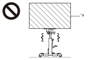
| *a | Object Exceeding Weight Limit of Transmission Jack |
Note
If automatic transaxle parts are replaced, refer to Parts Replacement Compensation Table to determine if any additional operations are necessary.
PROCEDURE
-
PRECAUTION
Note
After turning the ignition switch off, waiting time may be required before disconnecting the cable from the negative (-) battery terminal. Therefore, make sure to read the disconnecting the cable from the negative (-) battery terminal notices before proceeding with work.
-
ALIGN FRONT WHEELS FACING STRAIGHT AHEAD
-
SECURE STEERING WHEEL
-
DISCONNECT CABLE FROM NEGATIVE BATTERY TERMINAL
Note
When disconnecting the cable, some systems need to be initialized after the cable is reconnected.
-
REMOVE FRONT WHEELS
-
REMOVE WINDSHIELD WIPER MOTOR AND LINK ASSEMBLY
-
REMOVE OUTER COWL TOP PANEL SUB-ASSEMBLY
-
REMOVE STARTER ASSEMBLY
-
SEPARATE BRAKE MASTER CYLINDER RESERVOIR ASSEMBLY
-
REMOVE NO. 1 ENGINE UNDER COVER
-
REMOVE NO. 2 ENGINE UNDER COVER
-
REMOVE FRONT FLOOR COVER LH
-
SEPARATE FRONT FENDER LINER LH
-
SEPARATE FRONT FENDER LINER RH
-
REMOVE FRONT FENDER APRON SEAL LH
-
REMOVE FRONT FENDER APRON SEAL RH
-
SEPARATE STEERING INTERMEDIATE SHAFT ASSEMBLY
-
REMOVE FRONT DRIVE SHAFT ASSEMBLY
-
REMOVE FRONT EXHAUST PIPE ASSEMBLY
-
SEPARATE FRONT ENGINE MOUNTING INSULATOR
-
SEPARATE ENGINE MOUNTING INSULATOR LH
-
SEPARATE ENGINE MOUNTING INSULATOR RH
-
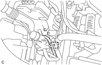
DISCONNECT WIRE HARNESS
-
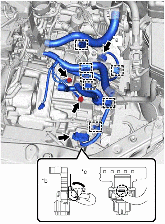
*a Park/Neutral Position Switch Assembly Connector *b Wiring Harness Connector *c Lever Disconnect the park/neutral position switch assembly connector.
-
Disengage the claw, rotate the lever and disconnect the connector of the wiring harness connector.
-
Remove the 2 bolts and disengage the 7 clamps to disconnect the wire harness from the automatic transaxle assembly.
-
-
DISCONNECT INLET NO. 1 OIL COOLER HOSE
-
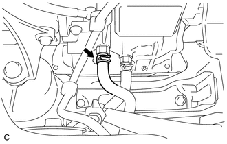
Slide the clip and disconnect the inlet No. 1 oil cooler hose from the automatic transaxle assembly.
-
-
DISCONNECT OUTLET NO. 1 OIL COOLER HOSE
-
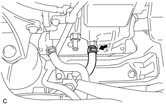
Slide the clip and disconnect the outlet No. 1 oil cooler hose from the automatic transaxle assembly.
-
-
REMOVE NO. 2 ENGINE MOUNTING STAY RH
-
INSTALL ENGINE HANGERS
-
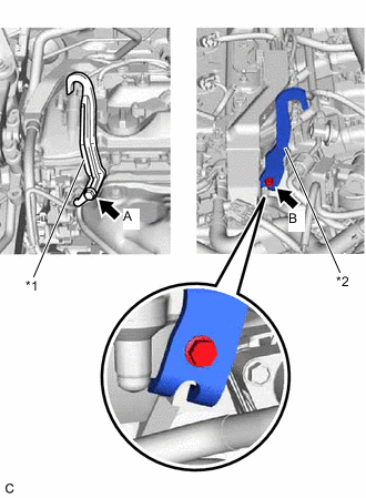
*1 No. 1 Engine Hanger *2 No. 2 Engine Hanger Install the No. 1 engine hanger and No. 2 engine hanger with the 2 bolts as shown in the illustration.
Part No. Item Part No. No. 1 Engine Hanger 12281-36020 No. 2 Engine Hanger 12282-36021 Bolt (A) 91552-81040 Bolt (B) 91552-81025 - Torque:
- 43 N*m { 438 kgf*cm, 32 ft.*lbf }
-
-
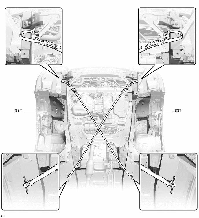
INSTALL ENGINE SUPPORT BRIDGE
-
Disengage the wire harness clamp.
-
Install SST to the vehicle body as shown in the illustration.
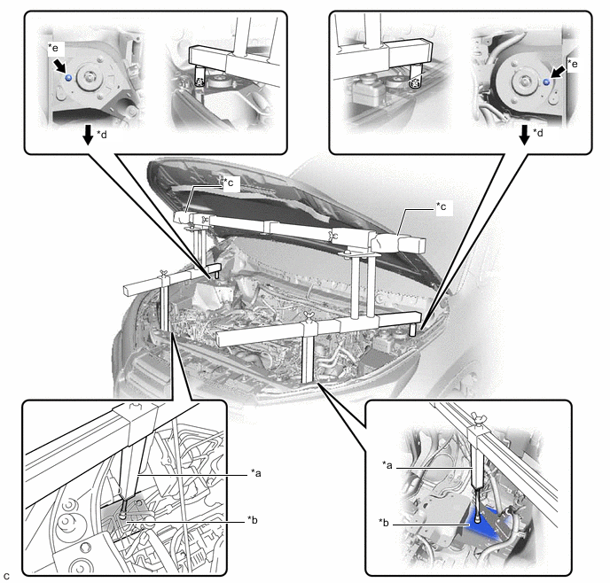
*a Support Shaft *b Front Side Member *c Cloth *d Front Side *e Front Suspension Nut - - - SST
- 09940-10020
CAUTION:
-
*a Support Shaft *b Front Side Member Make sure that no oil or grease is on the front side member, and set the support shaft on the level surface of the front side member.
-
The engine support bridge may fall off if there is any oil or grease on the front side member or it is installed on the unlevel surface.
Note
-
Prevent SST from contacting the vehicle body exterior and windshield glass.
-
To prevent damage to the engine hood, place pieces of cloth between the engine hood and SST.
-
Lightly shake SST by hand to make sure it is securely installed before performing work.
-
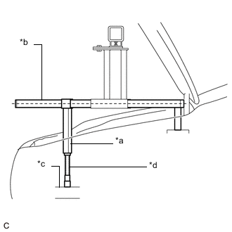
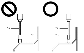
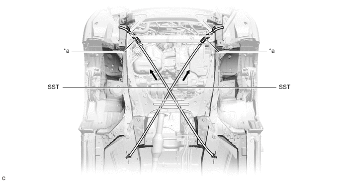
*a Support Shaft *b Sub Beam *c Front Side Member *d Threaded Portion Turn the threaded portion of each support shaft to adjust its height until the sub beams are parallel to the ground.
-
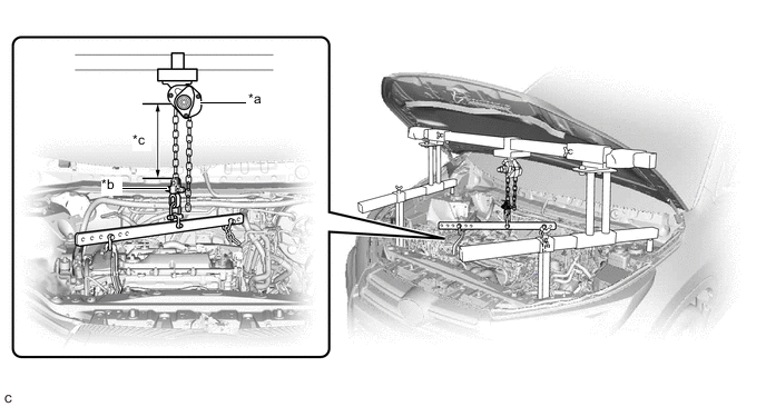
Install the chain block assembly to the sling bracket.

*a Chain Block Assembly *b Sling Bracket *c Fuse Shackle *d Shackle (A) -
Install the division bar to the chain block with the fuse shackle and shackle (A).
CAUTION:
-
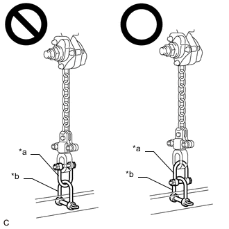
*a Fuse Shackle *b Shackle (A) Make sure the fuse shackle is on the chain block side and the shackle (A) is on the division bar side as shown in the illustration so that the fuse bolt is visible and can be checked for deformation easily.
-
If the fuse shackle is installed upside down, deformation of the fuse bolt will not be visible and cannot be used to tell if the load capacity of the engine support bridge has been exceeded. If the load capacity is exceeded, it may cause the engine support bridge to damage the vehicle and the engine assembly with automatic transaxle assembly may fall.
-
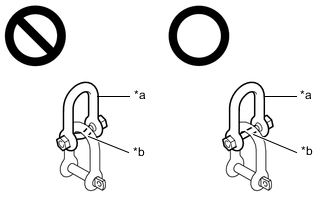
*a Fuse Shackle *b Fuse Bolt Make sure that the fuse bolt of the fuse shackle is free of damage, such as deformation or cracks. If damaged, replace the fuse shackle.
-
If a deformed fuse bolt is used, it cannot be used to tell if the load capacity of the engine support bridge has been exceeded. If the load capacity is exceeded, it may cause the engine support bridge to damage the vehicle and the engine assembly with transaxle assembly may fall.
-
-
Connect the division bar to the No. 1 engine hanger with the shackle (A).
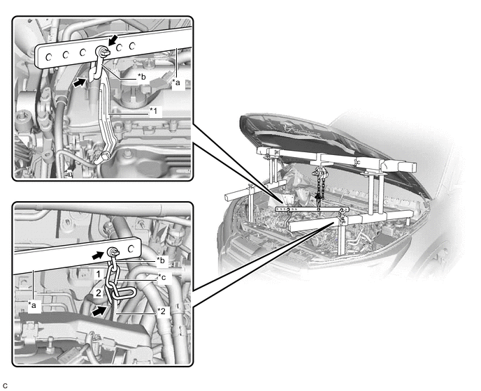
*1 No. 1 Engine Hanger *2 No. 2 Engine Hanger *a Division Bar *b Shackle (A) *c Chain - - -
Connect the division bar to the No. 2 engine hanger with the shackle (A) and chain.
Note
Connect the 2nd link of the chain to the No. 2 engine hanger.
-
Make sure the distance between the chain block assembly and suspension ring is 120 mm (4.72 in.) or more.
*a Chain Block Assembly *b Suspension Ring *c 120 mm or more - - Tech Tips
If the suspension height is less than 120 mm (4.72 in.), use a different link of the chain which connects the division bar and engine hanger.
-
Adjust the position of the chain block assembly so that the chain is perpendicular to the main beam and sub beams as shown in the illustration.
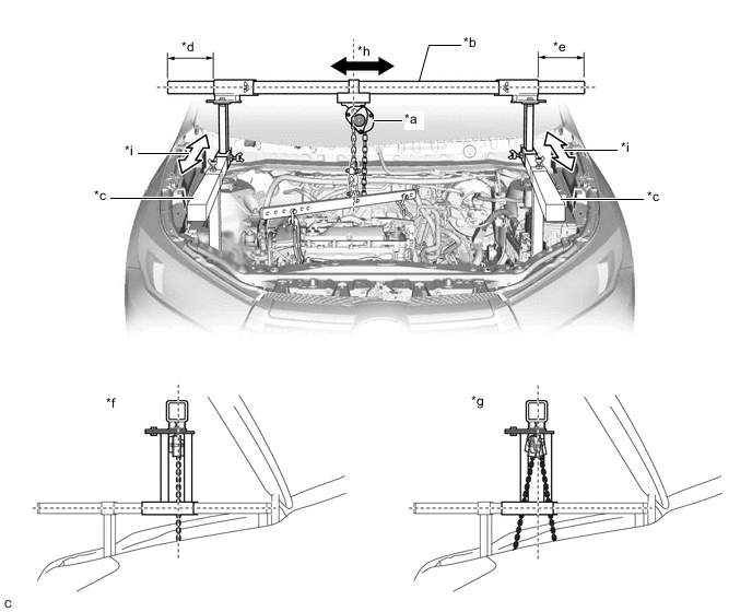
*a Chain Block Assembly *b Main Beam *c Sub Beam *d Dimension (A) *e Dimension (B) *f Correct *g Incorrect *h Right to Left Adjustment *i Front to Rear Adjustment - - CAUTION:
-
To prevent the engine assembly with automatic transaxle assembly from falling, make sure that the length of dimension (A) and dimension (B) are equal.
-
Do not perform any procedures if the length of dimension (A) and dimension (B) are not equal.
-
Performing any procedure when the length of dimension (A) and dimension (B) are not equal may cause the engine assembly with automatic transaxle assembly and engine support bridge to fall, possibly causing serious injury.
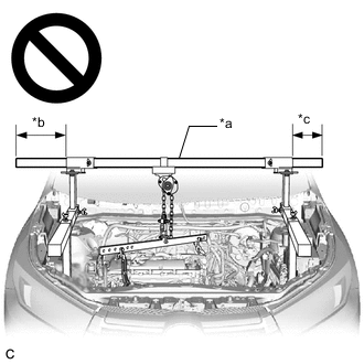
*a Main Beam *b Dimension (A) *c Dimension (B) -
-
Tighten the 6 wing bolts and 2 bolts.
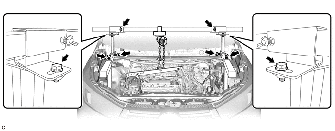
- Torque:
- 30 N*m { 306 kgf*cm, 22 ft.*lbf }
CAUTION:
-
Do not perform any procedures before tightening the bolts to the specified torque.
-
Performing procedures without tightening the bolts to the specified torque, may cause the engine support bridge to fall.
-
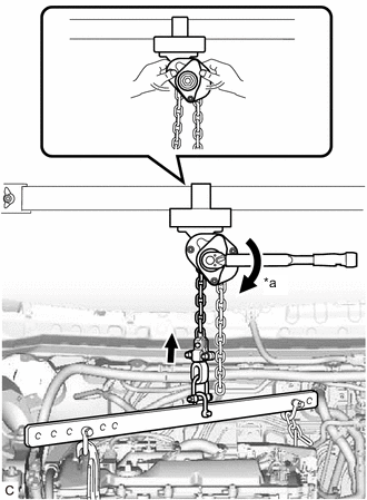
*a Turn Tighten the chain block assembly until it cannot be moved any further by hand.
-
-
REMOVE FLYWHEEL HOUSING UNDER COVER
-
REMOVE DRIVE PLATE AND TORQUE CONVERTER ASSEMBLY SETTING BOLT
-
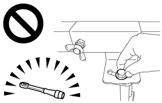
Turn the crankshaft to gain access to the removable locations of the 6 drive plate and torque converter assembly setting bolts and remove each drive plate and torque converter assembly setting bolt while holding the crankshaft pulley bolt with a wrench.
Tech Tips
There will be one black colored drive plate and torque converter assembly setting bolt.
-
-
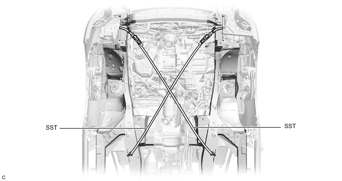
INSTALL BELT
-
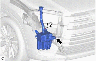

Bolt 
Nut Remove the bolt and nut and disconnect the windshield washer jar assembly from the vehicle body.
-
Install SST to the vehicle body as shown in the illustration.
- SST
- 09727-00110
-
Using the ratchet buckle, tighten the 2 belts until there is no slack.
*a Ratchet Buckle - -
-
-
REMOVE FRONT FRAME ASSEMBLY
-
REMOVE ENGINE MOUNTING INSULATOR RH
-
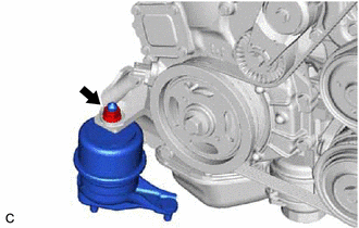
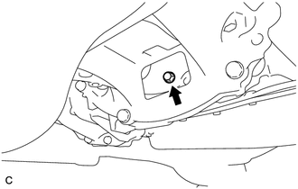
Remove the nut and engine mounting insulator RH from the engine mounting bracket RH.
-
-
INSTALL ENGINE SUPPORT BAR
-
Install SST (support bar) to the engine mounting bracket RH with the stud bolt and SST (nut).
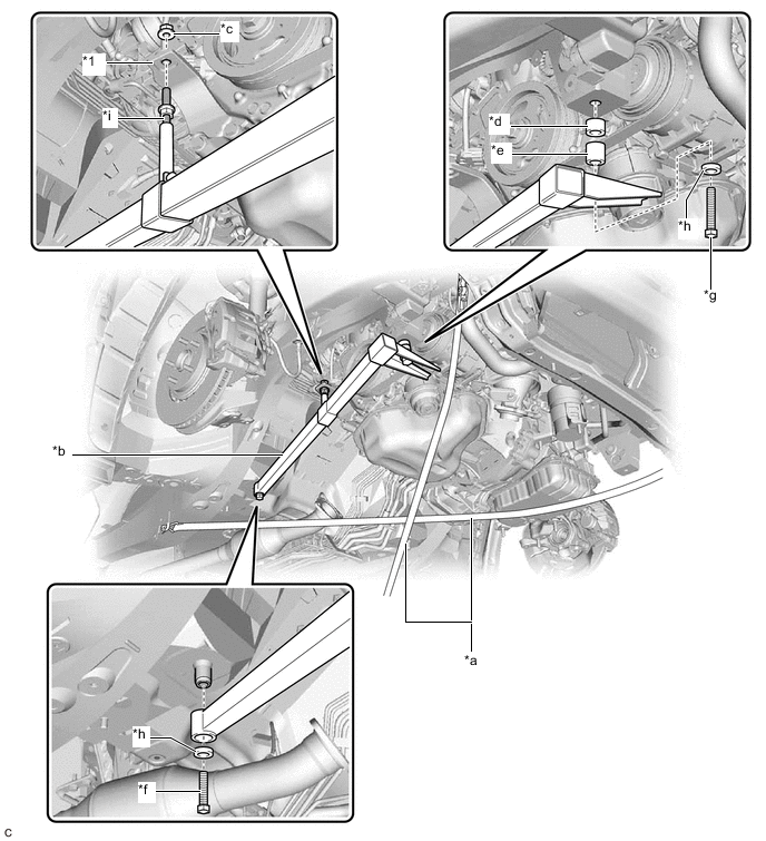
*1 Engine Mounting Bracket RH - - *a SST (Belt) *b SST (Support Bar) *c SST (Nut) *d SST (Spacer 20) *e SST (Spacer 30) *f SST (Bolt 40) *g SST (Bolt 90) *h SST (Washer) *i Stud Bolt - - - SST
- 09940-20011 ( 09941-02010, 09941-02020, 09941-02030, 09941-02040, 09941-02050, 09941-02060, 09941-02070 )
CAUTION:
To prevent the engine assembly with automatic transaxle assembly from falling while servicing, do not remove SST (belt).
Tech Tips
Tighten SST (nut) by hand.
-
Install SST (support bar) to the vehicle body with SST (bolt 40), SST (bolt 90) and 2 SST (washer) as shown in the illustration.
- Torque:
- 30 N*m { 306 kgf*cm, 22 ft.*lbf }
-
-
REMOVE FRONT ENGINE MOUNTING INSULATOR ASSEMBLY
-
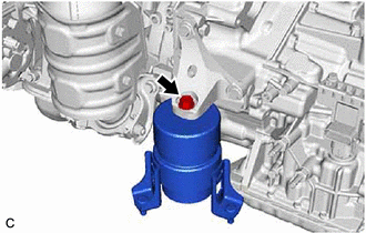
Remove the bolt and front engine mounting insulator assembly from the front engine mounting bracket.
-
-
REMOVE ENGINE MOUNTING INSULATOR LH
-
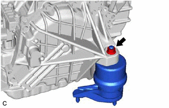
Remove the nut and engine mounting insulator LH from the automatic transaxle assembly.
-
-
SUPPORT ENGINE ASSEMBLY
-
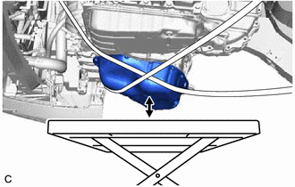
Set an engine lifter.
CAUTION:
To prevent the engine assembly with automatic transaxle assembly from falling while servicing, do not remove SST.
Note
Make sure that there is clearance between the engine oil pan assembly and engine lifter.
-
-
REMOVE BELT
-
Remove SST from the vehicle body.
-
-
REMOVE AUTOMATIC TRANSAXLE ASSEMBLY
-
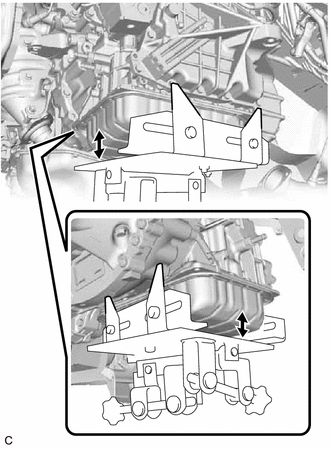
Support the automatic transaxle assembly with a transmission jack.
Note
-
In order to protect the automatic transaxle oil pan sub-assembly, place attachments on the transmission jack.
-
Make sure that the attachments and automatic transaxle oil pan sub-assembly are centered on the transmission jack.
-
To prevent the automatic transaxle oil pan sub-assembly from being deformed, do not place any attachments under the automatic transaxle oil pan sub-assembly.
-
Secure the automatic transaxle assembly to the transmission jack using a suitable adapter, such as a rope or attachment.
-
-
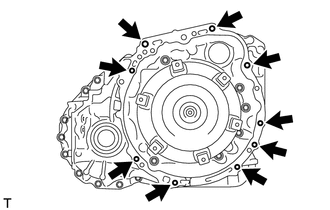
Remove the 9 bolts and automatic transaxle assembly.
Note
To prevent damage to the knock pins, do not pry between the automatic transaxle assembly and engine assembly.
-
-
REMOVE FRONT ENGINE MOUNTING BRACKET
-
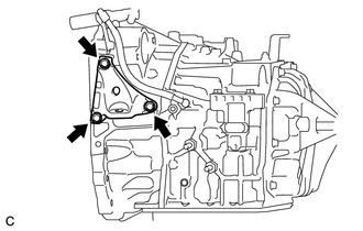
Remove the 3 bolts and front engine mounting bracket from the automatic transaxle assembly.
-
-
REMOVE WIRING HARNESS CONNECTOR
-
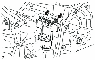
Remove the 2 bolts.
-
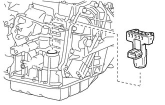
Remove the wiring harness connector from the automatic transaxle assembly.
-
-
REMOVE FLEXIBLE HOSE BRACKET SUB-ASSEMBLY
-
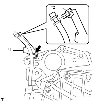
*1 Flexible Hose Bracket Sub-assembly *2 Clamp Disconnect the breather plug hose from the flexible hose bracket sub-assembly.
-
Remove the bolt and flexible hose bracket sub-assembly from the automatic transaxle assembly.
-
Remove the clamp from the flexible hose bracket sub-assembly.
-
-
REMOVE WIRE HARNESS CLAMP BRACKET
-
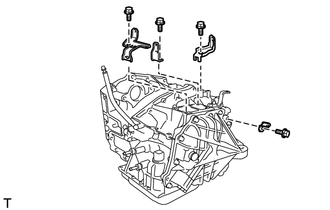
Remove the 4 bolts and 4 wire harness clamp brackets from the automatic transaxle assembly.
-
-
REMOVE NO. 1 TRANSMISSION CONTROL CABLE BRACKET
-
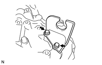
Remove the 2 bolts and No. 1 transmission control cable bracket from the automatic transaxle assembly.
-
-
REMOVE TRANSMISSION CASE PLUG ASSEMBLY
-
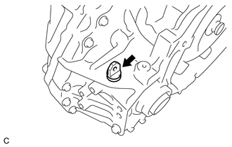
Remove the transmission case plug assembly from the automatic transaxle assembly.
-
-
REMOVE TORQUE CONVERTER ASSEMBLY
-
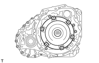
Remove the torque converter assembly from the automatic transaxle assembly.
Note
Remove the torque converter assembly from the input shaft horizontally.
-
-
INSPECT TORQUE CONVERTER ASSEMBLY
-
INSPECT DRIVE PLATE AND RING GEAR SUB-ASSEMBLY