AUTOMATIC TRANSAXLE ASSEMBLY(When Not Using the Engine Support Bridge) REMOVAL
CAUTION / NOTICE / HINT
CAUTION:
The engine assembly with automatic transaxle assembly is very heavy. Be sure to follow the procedure described in the repair manual, or the engine lifter may suddenly drop.
Note
If automatic transaxle parts are replaced, refer to Parts Replacement Compensation Table to determine if any additional operations are necessary.
PROCEDURE
-
REMOVE FLYWHEEL HOUSING UNDER COVER
-
REMOVE DRIVE PLATE AND TORQUE CONVERTER ASSEMBLY SETTING BOLT
-
Turn the crankshaft to gain access to the removable locations of the 6 drive plate and torque converter assembly setting bolts and remove each drive plate and torque converter assembly setting bolt while holding the crankshaft pulley bolt with a wrench.
Tech Tips
There will be one black colored drive plate and torque converter assembly setting bolt.
-
-
REMOVE ENGINE ASSEMBLY WITH TRANSAXLE
-
INSTALL ENGINE HANGERS
-
REMOVE FRONT FRAME ASSEMBLY
-
REMOVE WIRING HARNESS CONNECTOR
-
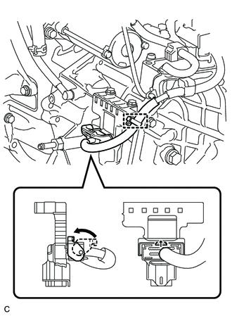
Disconnect the wire harness clamp.
-
Turn the lock lever and disconnect the wiring harness connector.
-
Remove the 2 bolts from the wiring harness connector.
-
Disconnect the wiring harness connector from the automatic transaxle assembly.
-
-
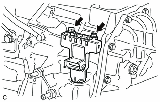
DISCONNECT WIRE HARNESS
-
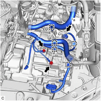
*a Park/Neutral Position Switch Connector Disconnect the park/neutral position switch connector.
-
Remove the 2 bolts and disengage the 5 clamps to disconnect the wire harness from the automatic transaxle assembly.
-
-
REMOVE AUTOMATIC TRANSAXLE ASSEMBLY
-
Using the transmission jack attachment, set the automatic transaxle assembly on a transmission jack.
Note
-
Secure the automatic transaxle assembly to the transmission jack using a suitable adapter, such as a rope or attachment.
-
To prevent the automatic transaxle oil pan sub-assembly from deforming, do not place any attachments onto the automatic transaxle oil pan sub-assembly of the automatic transaxle assembly.
-
Hold the engine assembly with a suitable adapter, such as a rope, during the operation.
-
-
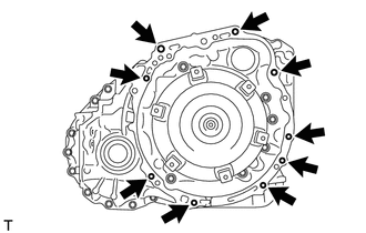
Remove the 9 bolts and automatic transaxle assembly.
Note
To prevent damage to the knock pins, do not pry between the automatic transaxle assembly and engine assembly.
-
-
REMOVE FRONT ENGINE MOUNTING BRACKET
-
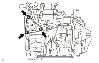
Remove the 3 bolts and front engine mounting bracket from the automatic transaxle assembly.
-
-
REMOVE FLEXIBLE HOSE BRACKET SUB-ASSEMBLY
-
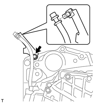
Disconnect the breather plug hose from the flexible hose bracket sub-assembly.
-
Remove the bolt and flexible hose bracket sub-assembly from the automatic transaxle assembly.
-
Remove the clamp from the flexible hose bracket sub-assembly.
-
-
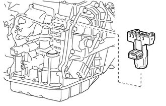
REMOVE WIRE HARNESS CLAMP BRACKET
-
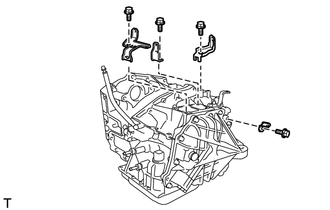
Remove the 4 bolts and 4 wire harness clamp brackets from the automatic transaxle assembly.
-
-
REMOVE NO. 1 TRANSMISSION CONTROL CABLE BRACKET
-
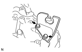
Remove the 2 bolts and No. 1 transmission control cable bracket from the automatic transaxle assembly.
-
-
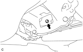
REMOVE TRANSMISSION CASE PLUG ASSEMBLY
-
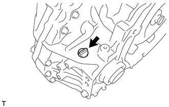
Remove the transmission case plug assembly from the automatic transaxle assembly.
-
Remove the O-ring from the transmission case plug assembly.
-
-
REMOVE TORQUE CONVERTER ASSEMBLY
-
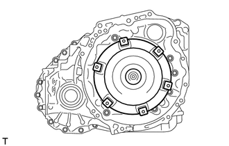
Remove the torque converter assembly from the automatic transaxle assembly.
Note
Remove the torque converter assembly from the input shaft horizontally.
-
-
INSPECT TORQUE CONVERTER ASSEMBLY
-
INSPECT DRIVE PLATE AND RING GEAR SUB-ASSEMBLY