VALVE BODY ASSEMBLY(When Using the Engine Support Bridge) INSTALLATION
PROCEDURE
-
INSTALL MANUAL VALVE
-
Coat the manual valve with ATF and install it to the transmission valve body assembly.
-
-
INSTALL NO. 1 GOVERNOR APPLY GASKET
-
Coat 2 new No. 1 governor apply gaskets with ATF.
-
Install the 2 No. 1 governor apply gaskets to the automatic transaxle assembly.
-
-
INSTALL TRANSMISSION VALVE BODY ASSEMBLY
-
Coat the O-ring of the transmission wire with ATF.
-
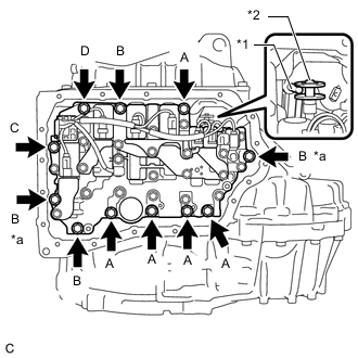
*1 Manual Valve Lever Shaft Sub-assembly *2 Manual Valve *a Positioning Bolt Insert the pin of the manual valve lever shaft sub-assembly into the groove on the end of the manual valve and install the transmission valve body assembly to the automatic transaxle assembly with the 11 bolts.
Bolt Length Bolt Length [mm (in.)] (A) 25 (0.984) (B) 30 (1.18) (C) and (D) 35 (1.38) - Torque:
- Bolt (A), (B), (C)
- 10.8 N*m { 110 kgf*cm, 8 ft.*lbf }
- Bolt (D)
- 9.6 N*m { 98 kgf*cm, 85 in.*lbf }
Note
-
When installing the transmission valve body assembly, be careful not to allow the transmission revolution sensor and automatic transaxle assembly to interfere with each other.
-
Be sure to insert the pin of the manual valve lever shaft sub-assembly into the groove on the end of the manual valve.
-
First, temporarily install the bolts marked (*a) in the illustration because they are positioning bolts.
-
-
INSTALL VALVE BODY OIL STRAINER ASSEMBLY
-
Coat a new O-ring with ATF and install it to the valve body oil strainer assembly.
Note
Ensure that the O-ring is not twisted.
-
Install the valve body oil strainer assembly to the transmission valve body assembly with the 2 bolts.
- Torque:
- 9.6 N*m { 98 kgf*cm, 85 in.*lbf }
-
-
INSTALL TRANSMISSION OIL CLEANER MAGNET
-
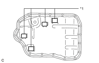
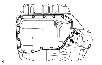
*1 Transmission Oil Cleaner Magnet Install the 4 transmission oil cleaner magnets to the automatic transaxle oil pan sub-assembly as shown in the illustration.
-
-
INSTALL AUTOMATIC TRANSAXLE OIL PAN GASKET
-
Install a new automatic transaxle oil pan gasket to the automatic transaxle oil pan sub-assembly.
-
-
INSTALL AUTOMATIC TRANSAXLE OIL PAN SUB-ASSEMBLY
-
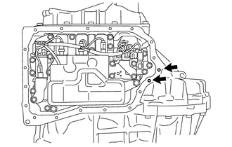
Clean and degrease the 2 bolts and installation holes in the automatic transaxle assembly.
-
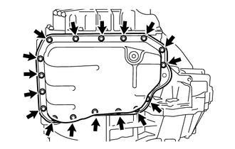
Install the automatic transaxle oil pan sub-assembly with automatic transaxle oil pan gasket to the automatic transaxle assembly with the 17 bolts.
- Torque:
- 7.5 N*m { 76 kgf*cm, 66 in.*lbf }
Note
Completely remove any oil or grease from the contact surfaces of the automatic transaxle assembly and automatic transaxle oil pan sub-assembly with automatic transaxle oil pan gasket before installation.
-
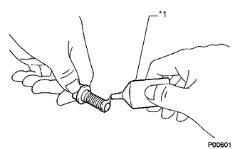
*1 Adhesive 1324 Apply adhesive to 2 or 3 threads on the ends of the 2 bolts.
Adhesive Toyota Genuine Adhesive 1324, Three Bond 1324 or equivalent Note
In order to ensure proper installation of the 2 bolts, apply adhesive to the 2 bolts and install them within 10 minutes of adhesive application.
-
Install the 2 bolts.
- Torque:
- 7.0 N*m { 71 kgf*cm, 62 in.*lbf }
-
-
INSTALL BELT
-
INSTALL FRONT FRAME ASSEMBLY
-
ADD AUTOMATIC TRANSAXLE FLUID
-
CHECK AUTOMATIC TRANSAXLE SYSTEM
Note
If automatic transaxle parts have been replaced, refer to Parts Replacement Compensation Table to determine if any additional operations are necessary.