FUEL TANK INSTALLATION
PROCEDURE
-
INSTALL TANK SUCTION TUBE SUPPORT
-
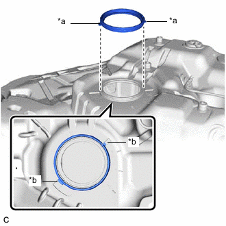
*a Protrusion *b Notch Install a new tank suction tube support to the fuel tank assembly.
Tech Tips
Align the protrusion of the tank suction tube support with the notch of the fuel tank assembly.
-
-
INSTALL FUEL TANK CUSHION SET
-
Install the 2 fuel tank cushion sets and 2 No. 5 fuel tank cushions to the fuel tank assembly.
-
-
INSTALL FUEL TANK TO FILLER PIPE HOSE
-
Install the fuel tank to filler pipe hose to the fuel tank assembly and tighten the clamp to secure it.
-
-
INSTALL FUEL TANK MAIN TUBE SUB-ASSEMBLY
-
Engage the 3 claws to install the fuel tank main tube sub-assembly to the fuel tank assembly.
-
-
INSTALL FUEL TANK SIDE PLATE
-
Install the fuel tank side plate to the fuel tank assembly with the fuel tank band pin and fuel tank cushion.
-
-
INSTALL FUEL TANK ASSEMBLY
-
Set the fuel tank assembly on an engine lifter.
Tech Tips
Using height adjustment attachments and plate lift attachments, place the fuel tank assembly horizontally.
-
Using the engine lifter, slowly raise the fuel tank assembly, and then install the fuel tank assembly with the No. 1 fuel tank band sub-assembly LH and No. 1 fuel tank band sub-assembly RH with the 4 bolts.
Note
-
Do not drop the fuel tank assembly.
-
When installing the fuel tank assembly, tilt it slightly to prevent it from interfering with the other surrounding parts.
- Torque:
- 39.2 N*m { 400 kgf*cm, 29 ft.*lbf }
-
-
Install the rear fuel tank bracket LH with the bolt and nut.
- Torque:
- Bolt
- 39.2 N*m { 400 kgf*cm, 29 ft.*lbf }
- Nut
- 19.6 N*m { 200 kgf*cm, 14 ft.*lbf }
-
Install the nut.
- Torque:
- 19.6 N*m { 200 kgf*cm, 14 ft.*lbf }
-
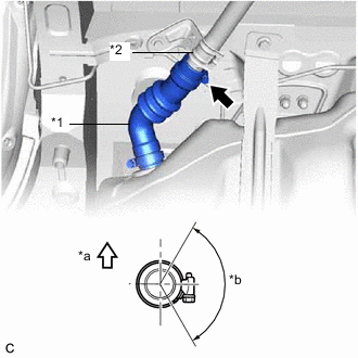
*1 Fuel Tank To Filler Pipe Hose *2 Fuel Tank To Filler Pipe Sub-assembly *a Upper *b 120° Connect the fuel tank to filler pipe hose to the fuel tank to filler pipe sub-assembly and tighten the clamp to secure it.
Tech Tips
Make sure the clamp bolt is within the area shown in the illustration.
-
-
CONNECT FUEL TANK BREATHER TUBE
-
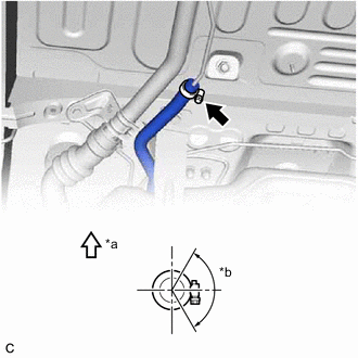
*a Upper *b 120° Connect the fuel tank breather tube to the fuel pipe and tighten the clamp to secure it.
Tech Tips
Make sure the clamp bolt is within the area shown in the illustration.
-
-
CONNECT FUEL TANK VENT HOSE SUB-ASSEMBLY
-
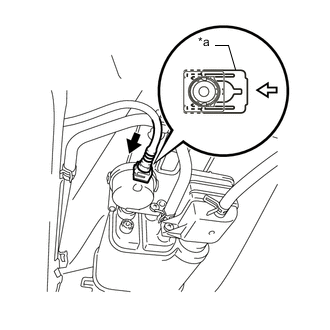
*a Retainer 
Push 
Push In Push the fuel tank vent hose sub-assembly onto the canister (charcoal canister assembly) and push in the retainer to engage the lock claws.
Note
-
Check that there are no scratches or foreign matter around the connecting parts of the fuel tank vent hose sub-assembly and pipe (canister (charcoal canister assembly)) before performing this work.
-
After connecting the fuel tank vent hose sub-assembly, check that the fuel tank vent hose sub-assembly is securely connected by pulling on the tube connector.
-
-
-
CONNECT FUEL TANK MAIN TUBE SUB-ASSEMBLY
-
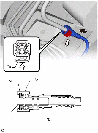
*a Retainer *b O-ring *c Fuel Tube Connector *d Fuel Pipe Push Push In Connect the fuel tank main tube sub-assembly.
Note
Check if there is any damage or foreign matter on the connecting parts of the fuel lines.
-
Align the fuel tube connector with the fuel pipe, and push them together until the fuel tube connector makes a "click" sound. If it is difficult to push the fuel pipe into the fuel tube connector, apply a small amount of clean engine oil to the tip of the fuel pipe and reinsert it.
-
Connect the fuel lines and push in the retainer. Check that the fuel pipe and fuel tube connector are securely connected by pulling on them.
-
-
-
INSTALL NO. 1 FUEL TANK PROTECTOR SUB-ASSEMBLY
-
Install the No. 1 fuel tank protector sub-assembly with the 7 nuts and 4 new clips.
- Torque:
- 5.5 N*m { 56 kgf*cm, 49 in.*lbf }
-
-
INSTALL CHARCOAL CANISTER PROTECTOR
-
INSTALL FRONT CENTER FLOOR COVER
-
Engage the 4 clips to install the front center floor cover.
-
Install the 2 screws and nut.
-
-
INSTALL REAR SUSPENSION MEMBER SUB-ASSEMBLY (for 2WD)
-
INSTALL REAR SUSPENSION MEMBER SUB-ASSEMBLY (for AWD)
-
INSTALL FUEL SUCTION TUBE WITH PUMP AND GAUGE ASSEMBLY