FUEL PUMP REMOVAL

CAUTION / NOTICE / HINT
PROCEDURE
-
PRECAUTION
Note
After turning the ignition switch off, waiting time may be required before disconnecting the cable from the negative (-) battery terminal. Therefore, make sure to read the disconnecting the cable from the negative (-) battery terminal notice before proceeding with work.
-
DISCHARGE FUEL SYSTEM PRESSURE
-
DISCONNECT CABLE FROM NEGATIVE BATTERY TERMINAL
Note
When disconnecting the cable, some systems need to be initialized after the cable is reconnected.
-
REMOVE REAR NO. 1 SEAT ASSEMBLY
for 60/40 Split Seat Type LH Side: Click here
for 60/40 Split Seat Type RH Side: Click here
-
REMOVE DECK BOARD ASSEMBLY
-
REMOVE NO. 3 DECK BOARD SUB-ASSEMBLY
-
REMOVE DECK SIDE TRIM BOX LH
-
REMOVE REAR DECK FLOOR BOX
-
REMOVE REAR FLOOR FINISH PLATE
-
REMOVE TONNEAU COVER ASSEMBLY
-
REMOVE REAR NO. 2 SEAT ASSEMBLY
-
REMOVE REAR DOOR SCUFF PLATE LH
-
REMOVE REAR DOOR OPENING TRIM WEATHERSTRIP LH
-
REMOVE REAR DOOR SCUFF PLATE RH
-
REMOVE REAR DOOR OPENING TRIM WEATHERSTRIP RH
-
REMOVE FRONT DECK SIDE TRIM COVER LH
-
DISCONNECT REAR NO. 1 SEAT OUTER BELT ASSEMBLY LH
-
REMOVE NO. 2 DECK SIDE TRIM COVER
-
REMOVE DECK TRIM SIDE SERVICE HOLE COVER
-
DISCONNECT REAR NO. 2 SEAT OUTER BELT ASSEMBLY LH
-
REMOVE DECK TRIM POCKET COVER (for LH Side)
-
REMOVE NO. 1 LUGGAGE COMPARTMENT TRIM HOOK (for LH Side)
-
REMOVE ROPE HOOK (for LH Side)
-
REMOVE DECK TRIM SIDE PANEL ASSEMBLY LH
-
REMOVE FRONT DECK SIDE TRIM COVER RH
-
DISCONNECT REAR NO. 1 SEAT OUTER BELT ASSEMBLY RH
-
REMOVE NO. 1 DECK SIDE TRIM COVER
-
REMOVE DECK TRIM SIDE BELT HOLE COVER RH
-
DISCONNECT REAR NO. 2 SEAT OUTER BELT ASSEMBLY RH
-
REMOVE SIDE TRIM COVER RH (w/o Rear Automatic Air Conditioning System)
-
REMOVE COOLER (NO. 2 ROOM TEMP. SENSOR) THERMISTOR
-
REMOVE NO. 1 ROOM LIGHT ASSEMBLY
-
REMOVE DECK TRIM POCKET COVER (for RH Side)
-
REMOVE NO. 1 LUGGAGE COMPARTMENT TRIM HOOK (for RH Side)
-
REMOVE ROPE HOOK (for RH Side)
-
REMOVE DECK TRIM SIDE PANEL ASSEMBLY RH
-
REMOVE REAR FLOOR SERVICE HOLE COVER
-
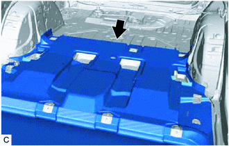
Turn back the front floor carpet.
-
Remove the rear floor service hole cover and butyl tape.
-
Disconnect the fuel pump connector.
-
-
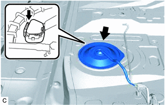
DISCONNECT FUEL TANK MAIN TUBE SUB-ASSEMBLY
-
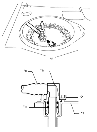
*1 Fuel Suction Plate Sub-assembly *2 Tube Joint Clip *a Fuel Tube Joint *b O-ring *c Nylon Tube 
Pull Off 
Pull Off Remove the tube joint clip, and pull off the fuel tube joint of the fuel tank main tube sub-assembly.
Note
-
Remove any foreign matter on the fuel tube joint before performing this work.
-
Do not allow any scratches or foreign matter to get on the parts when disconnecting them as the fuel tube joint has O-rings that seal the fuel pipe.
-
Only disconnect the fuel tube joint by hand.
-
Do not forcibly bend, twist or turn the nylon tube.
-
Protect the disconnected part by covering it with a plastic bag after disconnecting the fuel tube joint.
-
If the fuel tube joint and fuel suction plate sub-assembly are stuck, push and pull to release them.
-
-
-
REMOVE FUEL PUMP GAUGE RETAINER
Note
Before performing these procedures, first cover the connector and fuel tube joints of the fuel suction tube with pump and gauge assembly with vinyl tape and then clean any dirt and foreign matter in order to prevent contamination of the fuel system.
-
Install SST (fuel pump holding tool assy) to the fuel pump gauge retainer.
-
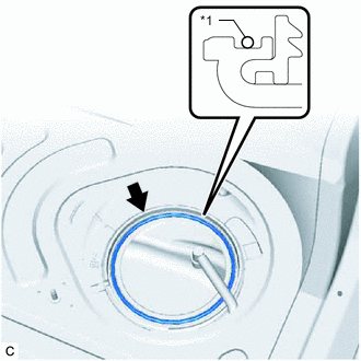
Insert SST (claw No. 1) between the service hole and fuel pump gauge retainer as shown in the illustration.
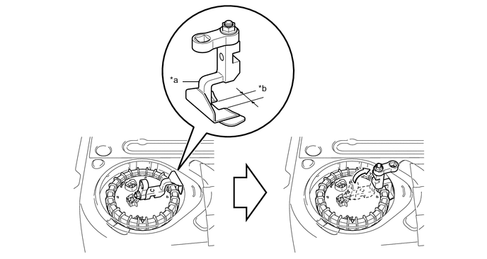
*a SST (Claw No. 1) *b Wide - SST
- 09808-14050 ( 09882-14050 )
-
Align the detent of the tank suction tube support and cut out of SST (claw No. 1).
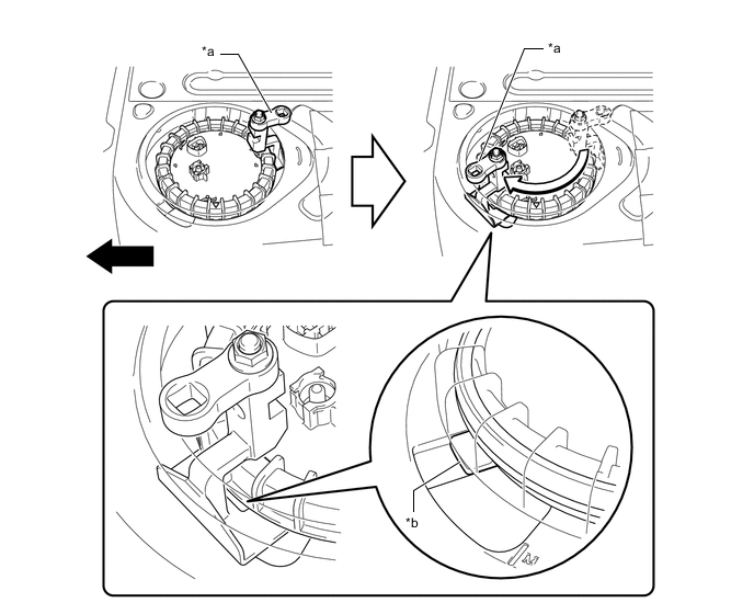
*a SST (Claw No. 1) *b Detent of Tank Suction Tube Support Front - - -
Insert SST (claw) between the service hole and fuel pump gauge retainer as shown in the illustration.
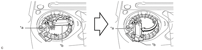
*a SST (Claw No. 1) *b SST (Claw) - SST
- 09808-14040 ( 09882-14040 )
-
Use the same procedure as for SST (claw No. 1), insert SST (claw No. 2) between the service hole and fuel pump gauge retainer, and align it with the second detent of the tank suction tube support.
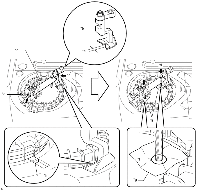
*a SST (Claw No. 1) *b SST (Claw No. 2) *c SST (Bridge) *d SST (Bolt) *e Narrow *f Contact *g Cloth *h Detent of Tank Suction Tube Support - SST
- 09808-14050 ( 09881-14050, 09882-14050, 09883-14050, 09884-14050 )
-
Install SST (bridge) to SST (claw No. 1) and SST (claw No. 2) with the 2 SST (bolt).
-
Place a piece of cloth or equivalent on the fuel suction tube with pump and gauge assembly and lightly tighten the 2 SST (bolt) of SST (bridge) until they come into contact with the fuel suction tube with pump and gauge assembly.
Note
If a piece of cloth or equivalent is not placed between the fuel suction tube with pump and gauge assembly and the 2 SST (bolt), the fuel suction tube with pump and gauge assembly may be damaged.
-
-
Install SST (fuel pump retainer tool assy) to the fuel pump gauge retainer.
-
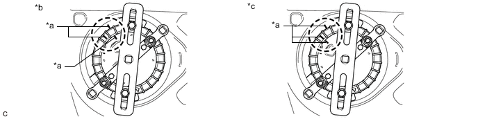
Position SST (claw) next to SST (claw No. 1) so that the protrusions of the fuel pump gauge retainer are aligned with the grooves of SST (claw). Use the same procedure as for the previous SST (claw), insert the second SST (claw) between the service hole and fuel pump gauge retainer, and position it next to SST (claw No. 2) so that it is opposite to SST (claw) and the protrusions of the fuel pump gauge retainer are aligned with the grooves of SST (claw).
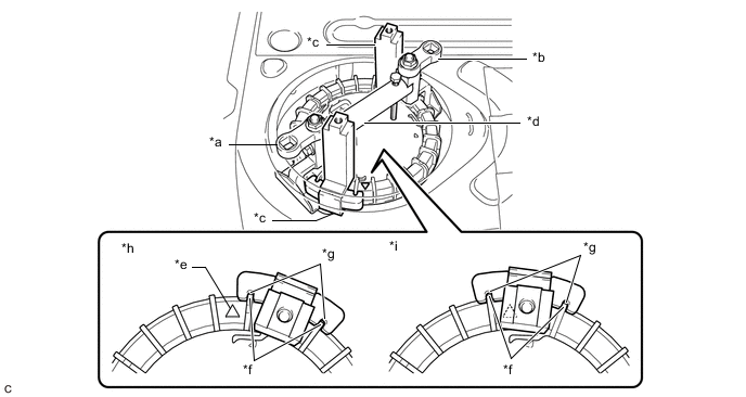
*a SST (Claw No. 1) *b SST (Claw No. 2) *c SST (Claw) *d SST (Bridge) *e Triangle Mark *f Protrusion of Fuel Pump Gauge Retainer *g Groove of SST (Claw) *h Correct *i Incorrect - - - SST
- 09808-14040 ( 09882-14040 )
Note
Ensure that SST (claw) does not cover the triangle mark of the fuel pump gauge retainer.
-
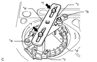
*a SST (Claw No. 1) *b SST (Claw No. 2) *c SST (Claw) *d SST (Bridge) *e SST (Plate) *f SST (Bolt and Washer Set) While ensuring that SST (plate) is centered, install SST (plate) to 2 SST (claw) with the 2 SST (bolt and washer set).
- SST
- 09808-14040 ( 09881-14040, 09883-14040 )
-
-
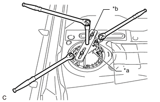
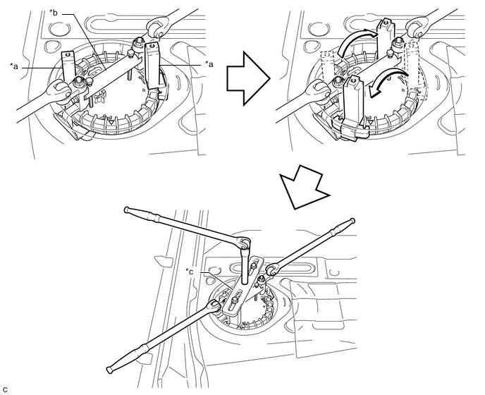
*a SST (Fuel Pump Holding Tool Assy) *b SST (Fuel Pump Retainer Tool Assy) Attach 2 breaker bars to SST (fuel pump holding tool assy) and 1 breaker bar to SST (fuel pump retainer tool assy).
-
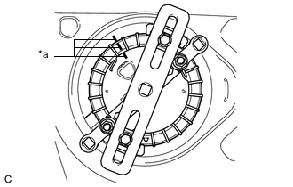
*a Paint Mark Place paint marks on the fuel suction tube with pump and gauge assembly, fuel pump gauge retainer and fuel tank assembly as shown in the illustration.
-
While holding the 2 breaker bars attached to SST (fuel pump holding tool assy), turn the breaker bar attached to SST (fuel pump retainer tool assy) to loosen the fuel pump gauge retainer. [*1]
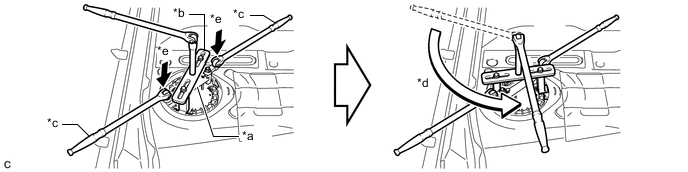
*a SST (Fuel Pump Holding Tool Assy) *b SST (Fuel Pump Retainer Tool Assy) *c Holding *d Turn *e Press down - - Note
Press down on the 2 locations shown in the illustration to prevent SST (fuel pump holding tool assy) from turning.
-
Check that only the paint mark on the fuel pump gauge retainer has moved.
*a Paint Mark *b Correct *c Incorrect - - Tech Tips
If the paint mark on the fuel suction tube with pump and gauge assembly has also moved, tighten the fuel pump gauge retainer until the paint marks are aligned at the original position. Then repeat from step [*1].
-
Loosen the fuel pump gauge retainer by using SST (fuel pump retainer tool assy) until the fuel pump gauge retainer turns approximately 360°.
*a SST (Claw) *b SST (Fuel Pump Holding Tool Assy) *c SST (Fuel Pump Retainer Tool Assy) - - -
Remove SST (fuel pump retainer tool assy) and SST (fuel pump holding tool assy) from the fuel pump gauge retainer.
-
Check that the fuel pump gauge retainer can be loosened by hand.
- SST
- 09808-14040 ( 09881-14040, 09882-14040, 09883-14040 )
-
While holding the fuel suction tube with pump and gauge assembly by hand, remove the fuel pump gauge retainer.
-
-
REMOVE FUEL SUCTION TUBE WITH PUMP AND GAUGE ASSEMBLY
-
Remove the fuel suction tube with pump and gauge assembly from the fuel tank assembly.
Note
Make sure that the fuel sender gauge arm does not bend.
-
*1 Fuel Suction Tube Set Gasket Remove the fuel suction tube set gasket from the fuel tank assembly.
-