ENGINE ASSEMBLY INSTALLATION
CAUTION / NOTICE / HINT
PROCEDURE
-
TEMPORARILY INSTALL REAR ENGINE MOUNTING INSULATOR ASSEMBLY
Tech Tips
Perform this procedure only when replacement of the rear engine mounting insulator assembly is necessary.
-
Temporarily install the rear engine mounting insulator with the 2 nuts.
-
-
TEMPORARILY INSTALL ENGINE MOUNTING INSULATOR RH
Tech Tips
Perform this procedure only when replacement of the engine mounting insulator RH is necessary.
-
Temporarily install the engine mounting insulator RH with the 3 nuts.
-
-
TEMPORARILY INSTALL ENGINE MOUNTING INSULATOR LH
Tech Tips
Perform this procedure only when replacement of the engine mounting insulator LH is necessary.
-
Temporarily install the engine mounting insulator LH with the 3 nuts.
-
-
TEMPORARILY INSTALL FRONT ENGINE MOUNTING INSULATOR ASSEMBLY
Tech Tips
Perform this procedure only when replacement of the front engine mounting insulator assembly is necessary.
-
Temporarily install the front engine mounting insulator assembly with the 3 nuts.
-
-
INSTALL ENGINE HANGERS
-
REMOVE ENGINE ASSEMBLY FROM ENGINE STAND
-
Using an engine sling device and engine lift, secure the engine assembly.
Note
-
Pay attention to the angle of the sling device as the engine assembly or No. 1 engine hanger and No. 2 engine hanger may be damaged or deformed if the angle is incorrect.
-
Do not perform any procedures while the engine assembly is suspended because doing so may cause the engine assembly to drop, resulting in injury. However, the engine assembly needs to be suspended when it is installed to or removed from an engine stand.
-
-
Remove the engine assembly from the engine stand.
-
-
INSTALL DRIVE PLATE AND RING GEAR SUB-ASSEMBLY
-
INSTALL ENGINE MOUNTING BRACKET RH
-
Install the engine mounting bracket RH to the cylinder block sub-assembly with the 3 bolts.
- Torque:
- 54 N*m { 551 kgf*cm, 40 ft.*lbf }
-
-
INSTALL AUTOMATIC TRANSAXLE ASSEMBLY
for 2WD: Click here
for AWD: Click here
-
INSTALL TRANSFER STIFFENER PLATE RH
-
INSTALL FRONT DRIVE SHAFT ASSEMBLY RH (for AWD)
-
INSTALL FRONT FRAME ASSEMBLY
-
Install the rear engine mounting insulator assembly with the 2 bolts.
- Torque:
- 75 N*m { 765 kgf*cm, 55 ft.*lbf }
-
Install the engine mounting insulator RH with the nut.
- Torque:
- 95 N*m { 969 kgf*cm, 70 ft.*lbf }
-
Install the engine mounting insulator LH with the nut.
- Torque:
- 95 N*m { 969 kgf*cm, 70 ft.*lbf }
-
Install the front engine mounting insulator assembly with the bolt.
- Torque:
- 87 N*m { 887 kgf*cm, 64 ft.*lbf }
-
Fully tighten the 11 temporarily installed nuts of the engine mounting insulators.
Tech Tips
Perform this procedure only when replacement of the engine mounting insulators is necessary.
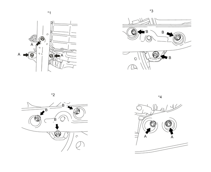
*1 Front Engine Mounting Insulator Assembly *2 Engine Mounting Insulator RH *3 Engine Mounting Insulator LH *4 Rear Engine Mounting Insulator - Torque:
- Nut (A)
- 58 N*m { 591 kgf*cm, 43 ft.*lbf }
- Torque:
- Nut (B)
- 99 N*m { 1010 kgf*cm, 73 ft.*lbf }
-
Install the 7 hole plugs to the front frame assembly.
Tech Tips
Perform this procedure only when replacement of the engine mounting insulators is necessary.
-
-
INSTALL STEERING LINK ASSEMBLY (for AWD)
-
INSTALL FRONT STABILIZER BAR (for AWD)
-
INSTALL FRONT NO. 1 STABILIZER BRACKET LH (for AWD)
-
INSTALL FRONT NO. 1 STABILIZER BRACKET RH (for AWD)
Tech Tips
Perform the same procedure as for the LH side.
-
INSTALL ENGINE WIRE
-
Install the engine wire to the engine assembly with transaxle.
-
-
INSTALL ENGINE ASSEMBLY WITH TRANSAXLE
-
Set the engine assembly with transaxle on the engine lifter.
Note
-
Using height adjustment attachments and plate lift attachments, place the engine assembly with transaxle horizontally.
-
Do not place any height adjustment attachments or plate lift attachments under the front frame assembly.
-
Servicing an engine assembly while it is hanging is dangerous. This can be done only when installing/removing the engine assembly to/from an engine stand.
-
To prevent the oil pan from deforming, do not place any attachments under the oil pan of the engine assembly with transaxle.
-
-
Remove the engine hangers.
-
Install the engine assembly with transaxle to the vehicle body.
Note
-
Do not raise the engine assembly with transaxle more than necessary. If the engine assembly with transaxle is raised excessively, the vehicle may also be lifted up.
-
Make sure that the engine assembly with transaxle is clear of all wiring and hoses.
-
While raising the engine assembly with transaxle into the vehicle, do not allow it to contact the vehicle.
-
-
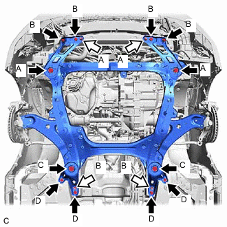

Bolt 
Nut Install the frame side rail plate RH and frame side rail plate LH to the front frame assembly and vehicle body with the 6 bolts and 2 nuts.
- Torque:
- Bolt (A)
- 85 N*m { 867 kgf*cm, 63 ft.*lbf }
- Bolt (B) and Nut (A)
- 32 N*m { 326 kgf*cm, 24 ft.*lbf }
-
Install the front suspension member rear brace RH and front suspension member rear brace LH to the front frame assembly and vehicle body with the 6 bolts and 2 nuts.
- Torque:
- Bolt (C)
- 85 N*m { 867 kgf*cm, 63 ft.*lbf }
- Bolt (D) and Nut (B)
- 32 N*m { 326 kgf*cm, 24 ft.*lbf }
-
-
INSTALL DRIVE PLATE AND TORQUE CONVERTER ASSEMBLY SETTING BOLT (for 2WD)
-
INSTALL DRIVE PLATE AND TORQUE CONVERTER ASSEMBLY SETTING BOLT (for AWD)
-
INSTALL FLYWHEEL HOUSING UNDER COVER
-
Install the flywheel housing under cover with the 2 bolts.
- Torque:
- 10 N*m { 102 kgf*cm, 7 ft.*lbf }
-
-
INSTALL FRONT DRIVE SHAFT HOLE SNAP RING (for LH Side)
-
INSTALL FRONT DRIVE SHAFT ASSEMBLY RH (for 2WD)
-
INSTALL FRONT DRIVE SHAFT ASSEMBLY LH
-
CONNECT FRONT LOWER NO. 1 SUSPENSION ARM SUB-ASSEMBLY LH
-
CONNECT FRONT LOWER NO. 1 SUSPENSION ARM SUB-ASSEMBLY RH
Tech Tips
Perform the same procedure as for the LH side.
-
INSTALL FRONT STABILIZER LINK ASSEMBLY LH
-
CONNECT FRONT STABILIZER LINK ASSEMBLY RH
Tech Tips
Perform the same procedure as for the LH side.
-
CONNECT TIE ROD ASSEMBLY LH
for 2WD: Click here
for AWD: Click here
-
CONNECT TIE ROD ASSEMBLY RH
Tech Tips
Perform the same procedure as for the LH side.
-
INSTALL FRONT SPEED SENSOR
-
CONNECT FRONT SPEED SENSOR RH
Tech Tips
Perform the same procedure as for the LH side.
-
INSTALL FRONT AXLE SHAFT NUT
-
INSTALL EXHAUST MANIFOLD
-
INSTALL NO. 1 EXHAUST PIPE SUPPORT BRACKET
-
Install the No. 1 exhaust pipe support bracket to the oil pan sub-assembly with the 2 nuts.
- Torque:
- 21 N*m { 214 kgf*cm, 15 ft.*lbf }
-
-
INSTALL FRONT EXHAUST PIPE ASSEMBLY
-
INSTALL FRONT NO. 3 EXHAUST PIPE SUB-ASSEMBLY
-
INSTALL PROPELLER WITH CENTER BEARING SHAFT ASSEMBLY (for AWD)
-
CONNECT SUCTION HOSE SUB-ASSEMBLY
-
CONNECT DISCHARGE HOSE SUB-ASSEMBLY
-
CONNECT STEERING INTERMEDIATE SHAFT ASSEMBLY
-
CONNECT TRANSMISSION CONTROL CABLE ASSEMBLY
-
Engage the transmission control cable assembly to the No. 3 transmission control cable bracket.
-
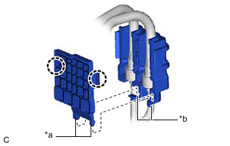
Install a new clip to the No. 1 transmission control cable bracket.
-
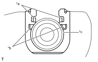
*a Claw A *b Claw B *c Transmission Control Cable Assembly Connect the transmission control cable assembly to the No. 1 transmission control cable bracket.
Note
-
Make sure that the claws A on the clip are securely fit into the No. 1 transmission control cable bracket holes.
-
Make sure that the transmission control cable assembly is securely installed inside of the claws B of the clip.
-
-
Connect the transmission control cable assembly to the transmission control shaft lever with the clip.
Note
Before connecting the transmission control cable assembly, check that the park/neutral position switch assembly and the shift lever are in neutral.
-
-
CONNECT ENGINE WIRE
-
Engage the 2 claws to connect the engine room main wire to the engine wire.
-
Install the engine room main wire with engine wire to the positive (+) battery terminal with the nut.
- Torque:
- 7.5 N*m { 76 kgf*cm, 66 in.*lbf }
-
Engage the clamp and connect the engine wire.
-
Connect the No. 3 earth wire with the bolt.
- Torque:
- 8.5 N*m { 87 kgf*cm, 75 in.*lbf }
-
Engage the 2 clamps.
-
Push down the lock lever to connect the ECM connector.
Note
-
When connecting the ECM connector, make sure that dirt, water or other foreign matter do not contact the connecting part of the ECM connector.
-
Be sure to securely connect the ECM connector.
-
-
Connect the 4 connectors to the engine room relay block assembly.
-
Engage 2 claws to connect the engine wire.
-
Engage the 2 clamps to connect the engine wire.
-
Install the engine wire to the engine room relay block assembly with the nut.
- Torque:
- 8.5 N*m { 87 kgf*cm, 75 in.*lbf }
-
Connect the earth wire with the bolt.
- Torque:
- 8.5 N*m { 87 kgf*cm, 75 in.*lbf }
-
Install the No. 1 relay block cover to the engine room relay block assembly.
-
-
INSTALL STARTER ASSEMBLY
-
CONNECT TRANSMISSION OIL THERMOSTAT
-
Connect the transmission oil thermostat to the oil cooler stay with the bolt.
- Torque:
- 19.5 N*m { 199 kgf*cm, 14 ft.*lbf }
-
-
CONNECT OUTLET NO. 1 OIL COOLER HOSE
-
Connect the outlet No. 1 oil cooler hose to the transmission oil thermostat and slide the clip to secure it.
-
-
CONNECT NO. 1 TRANSMISSION OIL COOLER HOSE
-
Connect the No. 1 transmission oil cooler hose to the transmission oil thermostat and slide the clip to secure it.
-
-
CONNECT FUEL TUBE SUB-ASSEMBLY
-
Connect the fuel tube sub-assembly (for Port Injection).
-
Connect the fuel tube sub-assembly to the fuel pipe.
-
-
Connect the No. 2 fuel tube sub-assembly (for Direct Injection).
-
Connect the No. 2 fuel tube sub-assembly to the fuel pipe.
-
-
Install the No. 1 fuel pipe clamp to the fuel tube connector.
-
Fuel Pipe Clamp Type A:
Install the No. 2 fuel pipe clamp to the No. 1 fuel pipe clamp.
-
*a Protrusion *b Notch Fuel Pipe Clamp Type B:
Align the protrusions of the No. 2 fuel pipe clamp with the notches of the No. 1 fuel pipe clamp, and engage the 2 claws to install the No. 2 fuel pipe clamp.
-
-
CONNECT NO. 4 WATER BY-PASS HOSE
-
Connect the No. 4 water by-pass hose to the radiator pipe assembly and slide the clip to secure it.
-
-
CONNECT NO. 3 WATER BY-PASS HOSE
-
Connect the No. 3 water by-pass hose to the radiator pipe assembly and slide the clip to secure it.
-
-
CONNECT WATER HOSE SUB-ASSEMBLY
-
Engage the clamp to the water hose sub-assembly.
-
Connect the 2 water hose sub-assemblies and slide the 2 clips to secure them.
-
-
CONNECT NO. 2 RADIATOR HOSE
-
Connect the No. 2 radiator hose to the water inlet and slide the clip to secure it.
-
-
CONNECT NO. 1 RADIATOR HOSE
-
Connect the No. 1 radiator hose to the radiator pipe clamp.
-
Connect the No. 1 radiator hose to the water outlet and slide the clip to secure it.
-
-
CONNECT UNION TO CHECK VALVE HOSE
-
for LHD
-
Engage the clamp to the union to check valve hose.
-
-
Connect the union to check valve hose to the intake air surge tank assembly and slide the clip to secure it.
-
-
CONNECT NO. 1 FUEL VAPOR FEED HOSE
-
Connect the No. 1 fuel vapor feed hose to the No. 1 vacuum switching valve and slide the clip to secure it.
-
Connect the purge VSV (purge valve) connector.
-
-
INSTALL ENGINE MOVING CONTROL ROD
Tech Tips
Perform this procedure only when replacement of the engine moving control rod or No. 3 engine mounting stay RH is necessary.
-
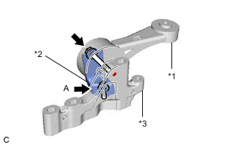
*1 Engine Moving Control Rod *2 No. 3 Engine Mounting Stay RH *3 Engine Moving Control Rod Bracket Temporarily install the No. 3 engine mounting stay RH and engine moving control rod to the engine moving control rod bracket with the 2 bolts.
-
Tighten the bolt (A).
- Torque:
- 78 N*m { 795 kgf*cm, 58 ft.*lbf }
-
-
INSTALL ENGINE MOVING CONTROL ROD BRACKET
-
When replacing the engine moving control rod.
-
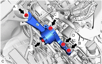
Install the engine moving control rod bracket with engine moving control rod with the 4 bolts.
- Torque:
- 38 N*m { 387 kgf*cm, 28 ft.*lbf }
Note
Temporarily tighten the bolt (A) and (B), and then fully tighten the 4 bolts in the order of (C), (D), (A) and (B).
-
Tighten the bolt (E).
- Torque:
- 52 N*m { 530 kgf*cm, 38 ft.*lbf }
-
-
When not replacing the engine moving control rod.
-
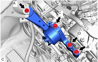
Install the engine moving control rod bracket with engine moving control rod with the 4 bolts.
- Torque:
- 38 N*m { 387 kgf*cm, 28 ft.*lbf }
Note
Temporarily tighten the bolt (A) and (B), and then fully tighten the 4 bolts in the order of (C), (D), (A) and (B).
-
-
-
INSTALL NO. 2 ENGINE MOUNTING STAY RH
-
Install the No. 2 engine mounting stay RH to the engine mounting insulator sub-assembly RH with the bolt and 2 nuts.
- Torque:
- Bolt
- 38 N*m { 387 kgf*cm, 28 ft.*lbf }
- Nut
- 23 N*m { 235 kgf*cm, 17 ft.*lbf }
-
-
INSTALL AIR CLEANER BRACKET
-
Install the air cleaner bracket to the vehicle body with the 2 bolts.
- Torque:
- 8.0 N*m { 82 kgf*cm, 71 in.*lbf }
-
Engage the clamp.
-
-
INSTALL RESERVOIR BRACKET (for LHD)
-
INSTALL BRAKE MASTER CYLINDER RESERVOIR ASSEMBLY (for LHD)
-
INSTALL RESERVOIR BRACKET (for RHD)
-
INSTALL BRAKE MASTER CYLINDER RESERVOIR ASSEMBLY (for RHD)
-
INSTALL AIR CLEANER ASSEMBLY WITH AIR CLEANER HOSE
-
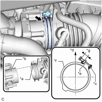
*a Cutout *b Protrusion *c Hose Clamp *d Up *e Stopper *f Air Cleaner Hose Assembly *g 5.0 to 9.0 mm (0.197 to 0.354 in.) Install the air cleaner assembly with air cleaner hose to the throttle body with motor assembly.
Note
Align the cutout of the air cleaner hose assembly with the protrusion of the throttle body with motor assembly.
-
Tighten the hose clamp in the position shown in the illustration.
Tech Tips
Make sure that the hose clamp is positioned as shown in the illustration.
-
Install the 2 bolts.
- Torque:
- 5.0 N*m { 51 kgf*cm, 44 in.*lbf }
-
Connect the No. 2 ventilation hose to the air cleaner hose assembly and slide the clip to secure it.
-
Engage the No. 1 fuel vapor feed hose to the air cleaner hose assembly.
-
Engage the wire harness clamp.
-
Connect the mass air flow meter sub-assembly connector.
-
-
INSTALL INLET AIR CLEANER ASSEMBLY
-
Install the inlet air cleaner assembly with the 2 bolts.
- Torque:
- 8.0 N*m { 82 kgf*cm, 71 in.*lbf }
-
-
INSTALL BATTERY
-
Install the battery and battery tray.
-
Install the battery clamp and battery clamp bolt with the bolt and nut.
- Torque:
- 5.4 N*m { 55 kgf*cm, 48 in.*lbf }
-
Connect the cable to the positive (+) battery terminal.
- Torque:
- 6.5 N*m { 66 kgf*cm, 58 in.*lbf }
-
-
CONNECT CABLE TO NEGATIVE BATTERY TERMINAL
-
Connect the cable to the negative (-) battery terminal.
- Torque:
- 6.5 N*m { 66 kgf*cm, 58 in.*lbf }
Note
When disconnecting the cable, some systems need to be initialized after the cable is reconnected.
-
-
INSTALL FRONT WHEELS
- Torque:
- 103 N*m { 1050 kgf*cm, 76 ft.*lbf }
-
ADD ENGINE OIL
-
ADD ENGINE COOLANT
-
ADD AUTOMATIC TRANSAXLE FLUID (for 2WD)
-
ADD AUTOMATIC TRANSAXLE FLUID (for AWD)
-
ADD TRANSFER OIL (for AWD)
-
CHARGE AIR CONDITIONING SYSTEM WITH REFRIGERANT
-
WARM UP ENGINE
-
INSPECT FOR REFRIGERANT LEAK
-
CHECK ENGINE OIL LEVEL
-
INSPECT ENGINE COOLANT LEVEL IN RESERVOIR TANK
-
INSPECT FOR FUEL LEAK
-
INSPECT FOR COOLANT LEAK
-
INSPECT FOR OIL LEAK
-
INSPECT FOR EXHAUST GAS LEAK
-
INSPECT IGNITION TIMING
-
INSPECT ENGINE IDLE SPEED
-
INSPECT CO/HC
-
CHECK FOR SPEED SENSOR SIGNAL
-
INSPECT SHIFT LEVER POSITION (for 2WD)
-
INSPECT SHIFT LEVER POSITION (for AWD)
-
ADJUST SHIFT LEVER POSITION (for 2WD)
-
ADJUST SHIFT LEVER POSITION (for AWD)
-
INSPECT AND ADJUST FRONT WHEEL ALIGNMENT
-
INSTALL V-BANK COVER SUB-ASSEMBLY
-
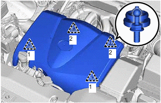
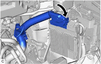
Engage the 4 clips in the order shown in the illustration to install the V-bank cover sub-assembly.
Note
-
Securely engage the clips.
-
If the clips are forcibly engaged or struck with an object, they may be damaged.
-
-
-
INSTALL COOL AIR INTAKE DUCT SEAL
-
INSTALL RADIATOR SIDE SEAL RH
-
INSTALL RADIATOR SIDE DEFLECTOR SEAL LH
-
INSTALL OUTER COWL TOP PANEL SUB-ASSEMBLY
for LHD: Click here
for RHD: Click here
-
INSTALL WINDSHIELD WIPER MOTOR AND LINK ASSEMBLY
-
INSTALL FRONT FENDER APRON SEAL LH
-
Install the front fender apron seal LH with the 2 bolts and clip.
-
-
INSTALL FRONT FENDER APRON SEAL RH
-
Install the front fender apron seal RH with the 2 bolts and clip.
-
-
INSTALL FRONT FENDER LINER LH
-
Install the front fender liner LH with the 3 screws and 3 clips.
-
-
INSTALL FRONT FENDER LINER RH
-
Install the front fender liner RH with the 3 screws and 3 clips.
-
-
INSTALL FRONT FLOOR COVER LH
-
INSTALL NO. 2 ENGINE UNDER COVER
-
Install the No. 2 engine under cover with the 2 bolts, 2 screws and clip.
-
-
INSTALL NO. 1 ENGINE UNDER COVER
-
Install the No. 1 engine under cover with the 8 bolts, 6 screws and 3 clips.
-