CYLINDER BLOCK REPLACEMENT

PROCEDURE
-
REPLACE STRAIGHT PIN
-
Using a plastic hammer, tap in new straight pins to the cylinder block sub-assembly.
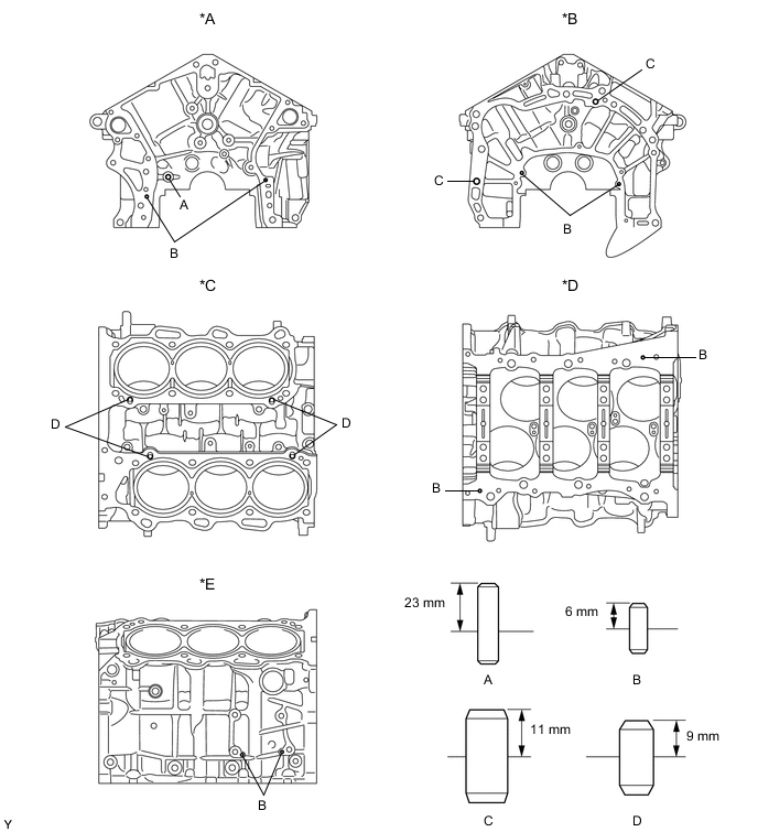
*A Front Side *B Rear Side *C Upper Side *D Lower Side *E RH Side - - Standard Protrusion Item Protrusion Pin A 23 mm (0.906 in.) Pin B 6 mm (0.236 in.) Pin C 11 mm (0.433 in.) Pin D 9 mm (0.354 in.)
-
-
REPLACE STUD BOLT
-
Using E8 and E10 "TORX" socket wrenches, install the stud bolts.
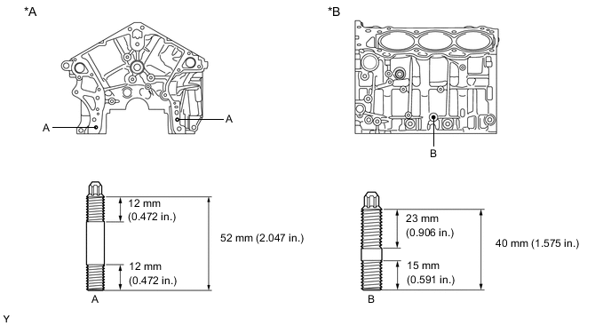
*A Front Side *B LH Side - Torque:
- Bolt (A)
- 10 N*m { 102 kgf*cm, 7 ft.*lbf }
- Bolt (B)
- 17 N*m { 173 kgf*cm, 13 ft.*lbf }
-
-
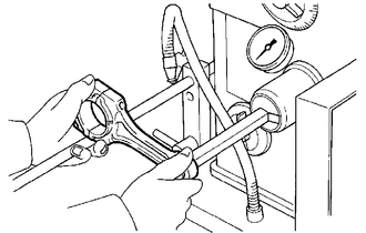
REPLACE CONNECTING ROD SMALL END BUSH
-
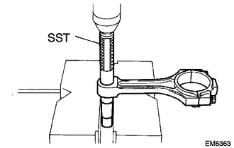
Using SST and a press, press out the bush.
- SST
- 09222-30010
-
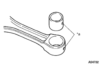
*a Oil Hole Align the oil holes of a new bush and the connecting rod.
-
Using SST and a press, press in the bush.
- SST
- 09222-30010
-
Using a pin hole grinder, hone the bush to obtain the standard oil clearance between the bush and piston pin.
Standard Oil Clearance 0.001 to 0.007 mm (0.0000394 to 0.000276 in.) -
Coat the piston pin with engine oil, and push it into the connecting rod with a thumb.
Tech Tips
Check that the piston pin fits at a normal room temperature.
-