ENGINE ASSEMBLY REMOVAL
PROCEDURE
-
PRECAUTION
CAUTION:
The engine assembly with transmission is very heavy. Be sure to follow the procedure described in the repair manual, or the engine lifter may suddenly drop.
Note
After turning the engine switch off, waiting time may be required before disconnecting the cable from the negative (-) battery terminal. Therefore, make sure to read the disconnecting the cable from the negative (-) battery terminal notices before proceeding with work.
-
RECOVER REFRIGERANT FROM REFRIGERATION SYSTEM
-
DISCHARGE FUEL SYSTEM PRESSURE
-
ALIGN FRONT WHEELS FACING STRAIGHT AHEAD
-
SECURE STEERING WHEEL
-
DISCONNECT CABLE FROM NEGATIVE BATTERY TERMINAL
Note
When disconnecting the cable, some systems need to be initialized after the cable is reconnected.
-
REMOVE FRONT WHEELS
-
REMOVE NO. 1 ENGINE UNDER COVER
-
Remove the 8 bolts, 6 screws, 3 clips and No. 1 engine under cover.
-
-
REMOVE NO. 2 ENGINE UNDER COVER
-
Remove the 2 bolts, 2 screws, clip and No. 2 engine under cover.
-
-
REMOVE FRONT FLOOR COVER LH
-
SEPARATE FRONT FENDER LINER LH
-
Remove the 3 screws and 3 clips and separate the front fender liner LH.
-
-
SEPARATE FRONT FENDER LINER RH
-
Remove the 3 screws and 3 clips and separate the front fender liner RH.
-
-
REMOVE FRONT FENDER APRON SEAL LH
-
Remove the 2 bolts, clip and front fender apron seal LH.
-
-
REMOVE FRONT FENDER APRON SEAL RH
-
Remove the 2 bolts, clip and front fender apron seal RH.
-
-
DRAIN ENGINE OIL
-
DRAIN ENGINE COOLANT
-
DRAIN AUTOMATIC TRANSAXLE FLUID (for 2WD)
-
DRAIN AUTOMATIC TRANSAXLE FLUID (for AWD)
-
DRAIN TRANSFER OIL (for AWD)
-
REMOVE WINDSHIELD WIPER MOTOR AND LINK ASSEMBLY
-
REMOVE OUTER COWL TOP PANEL SUB-ASSEMBLY (for LHD)
-
REMOVE OUTER COWL TOP PANEL SUB-ASSEMBLY (for RHD)
-
REMOVE RADIATOR SIDE DEFLECTOR SEAL LH
-
REMOVE RADIATOR SIDE SEAL RH
-
REMOVE COOL AIR INTAKE DUCT SEAL
-
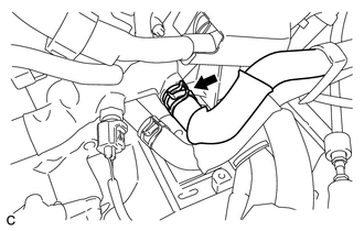
REMOVE V-BANK COVER SUB-ASSEMBLY
-
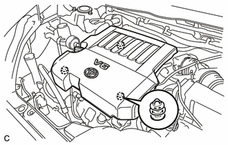
Hold the rear of the V-bank cover sub-assembly and raise it to disengage the 2 front retainers.
-
Raise the V-bank cover sub-assembly to disengage the rear retainer to remove the V-bank cover sub-assembly.
Note
Attempting to disengage both front and rear retainers at the same time may cause the V-bank cover sub-assembly to break.
-
-
REMOVE INLET AIR CLEANER ASSEMBLY
-
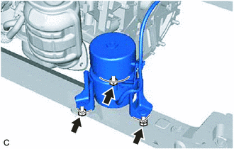
Remove the 2 bolts and inlet air cleaner assembly.
-
Separate the air hose from the 2 hose clamps.
-
-
REMOVE AIR CLEANER CAP WITH AIR CLEANER HOSE
-
REMOVE AIR CLEANER FILTER ELEMENT SUB-ASSEMBLY
-
Remove the air cleaner filter element sub-assembly from the air cleaner case sub-assembly.
-
-
REMOVE AIR CLEANER CASE SUB-ASSEMBLY
-
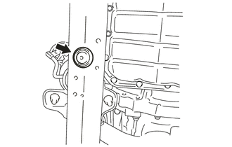
Remove the 2 bolts and air cleaner case sub-assembly.
-
-
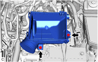
REMOVE BATTERY
-
Disconnect the cable from the positive (+) battery terminal.
-
Remove the nut and bolt.
-
Remove the battery clamp, battery clamp bolt, battery and battery tray.
-
-
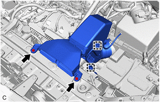
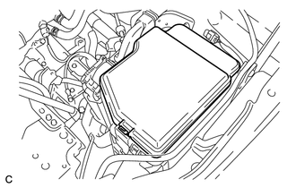
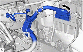
SEPARATE BRAKE MASTER CYLINDER RESERVOIR ASSEMBLY (for LHD)
-
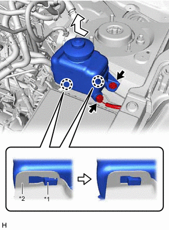
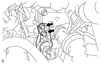
*1 Brake Master Cylinder Reservoir Assembly *2 Reservoir Bracket Disconnect the reservoir level switch connector and remove the bolt from the brake master cylinder reservoir assembly.
-
Move the brake master cylinder reservoir assembly as shown in the illustration to disengage the 2 claws, and separate it.
-
-
REMOVE RESERVOIR BRACKET (for LHD)
-
SEPARATE BRAKE MASTER CYLINDER RESERVOIR ASSEMBLY (for RHD)
-
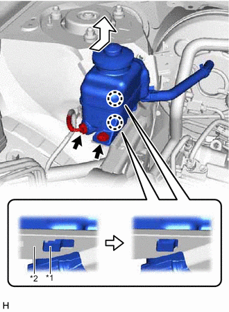
*1 Brake Master Cylinder Reservoir Assembly *2 Reservoir Bracket Disconnect the reservoir level switch connector and remove the bolt from the brake master cylinder reservoir assembly.
-
Move the brake master cylinder reservoir assembly as shown in the illustration to disengage the 2 claws, and separate it.
-
-
REMOVE RESERVOIR BRACKET (for RHD)
-
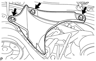
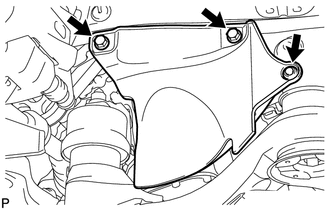
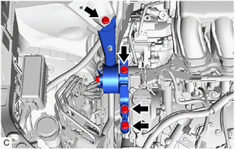
REMOVE NO. 2 ENGINE MOUNTING STAY RH
-
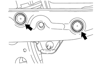
Remove the bolt, 2 nuts and No. 2 engine mounting stay RH.
-
-
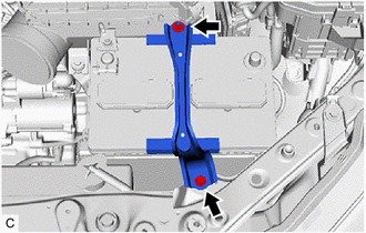
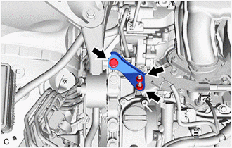
REMOVE ENGINE MOVING CONTROL ROD BRACKET
-
Remove the 4 bolts and engine moving control rod bracket with engine moving control rod.
-
-
REMOVE ENGINE MOVING CONTROL ROD
Tech Tips
Perform this procedure only when replacement of the engine moving control rod or No. 3 engine mounting stay RH is necessary.
-
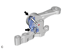
Remove the 2 bolts, engine moving control rod and No. 3 engine mounting stay RH from the engine moving control rod bracket.
-
-
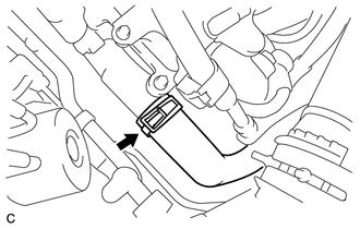
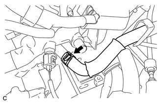
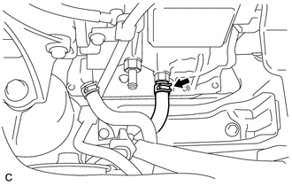
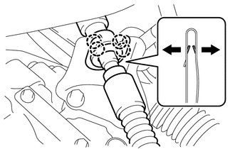
DISCONNECT NO. 1 FUEL VAPOR FEED HOSE
-
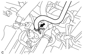
Slide the clip and disconnect the No. 1 fuel vapor feed hose from the No. 1 vacuum switching valve.
-
-
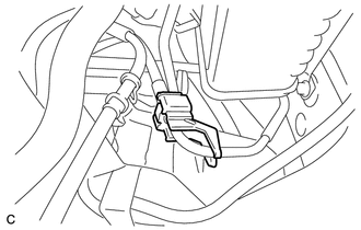
DISCONNECT UNION TO CHECK VALVE HOSE
-
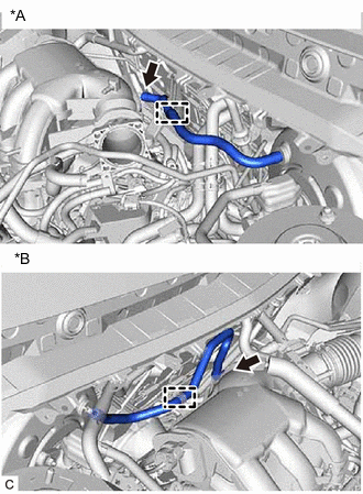
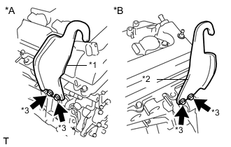
*A for LHD *B for RHD Slide the clip and disconnect the union to check valve hose from the intake air surge tank assembly.
-
-
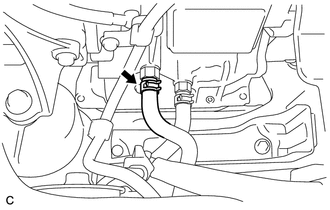
DISCONNECT NO. 1 RADIATOR HOSE
-
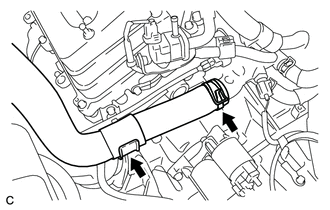
Slide the clip and disconnect the No. 1 radiator hose from the water outlet.
-
Separate the No. 1 radiator hose from the radiator pipe clamp.
-
-
DISCONNECT NO. 2 RADIATOR HOSE
-
Slide the clip and disconnect the No. 2 radiator hose from the water inlet.
-
-
DISCONNECT INLET HEATER WATER HOSE
-
Slide the clip and disconnect the inlet heater water hose from the water inlet.
-
-
DISCONNECT OUTLET HEATER WATER HOSE
-
Slide the clip and disconnect the outlet heater water hose from the water outlet.
-
-
DISCONNECT FUEL TUBE SUB-ASSEMBLY
-
Remove the No. 1 fuel pipe clamp.
-
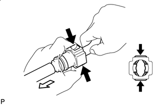

Push 
Pull Disconnect the connector from the fuel main tube by hand. When the connector and the fuel main tube are stuck, push and pull the connector to release it. Pull the connector off of the fuel main tube carefully.
Note
-
Check for any dirt and foreign matter in the fuel main tube and around the connector. Clean if necessary. Foreign matter may damage the O-rings or cause leaks in the seal between the fuel main tube and connector.
-
Do not use any tools to separate the fuel main tube and connector.
-
Do not forcibly bend or twist the nylon tube.
-
Check for any dirt and foreign matter on the tube seal surface. Clean if necessary.
-
Cover the fuel main tube and connector ends with plastic bags to prevent damage and contamination.
-
If the fuel main tube and connector are stuck together, pinch the fuel main tube between your fingers and turn it carefully to free it. Then disconnect the fuel main tube.
-
-
-
DISCONNECT NO. 1 OUTLET OIL COOLER HOSE
-
Slide the clip and disconnect the No. 1 outlet oil cooler hose.
-
-
DISCONNECT NO. 1 INLET OIL COOLER HOSE
-
Slide the clip and disconnect the No. 1 inlet oil cooler hose.
-
-
REMOVE STARTER ASSEMBLY
-
DISCONNECT ENGINE WIRE
-
Remove the No. 1 relay block cover from the engine room relay block assembly.
-
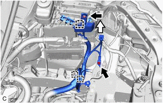
Remove the bolt and separate the earth wire.
-
Remove the nut from the engine room relay block assembly.
-
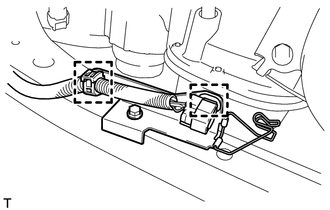
Disconnect the 3 wire clamps.
-
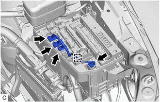
Disconnect the 4 connectors from the engine room relay block assembly.
-
Using a screwdriver, disengage the claw and separate the engine wire from the engine room relay block assembly.
-
Pull up the lock lever while pushing the lock on the lever to disconnect the ECM connector.
Note
After disconnecting the ECM connector, make sure that dirt, water or other foreign matter does not contact the connecting part of the ECM connector.
-
Disengage the 2 wire harness clamps.
-
-
SEPARATE TRANSMISSION CONTROL CABLE ASSEMBLY
-
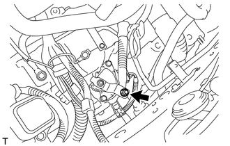
Remove the nut from the transmission control shaft lever.
-
Using a screwdriver, disengage the 4 claws, separate the transmission control cable assembly with clip from the No. 1 transmission control cable bracket.
-
Remove the clip from the transmission control cable assembly.
-
-
REMOVE PROPELLER WITH CENTER BEARING SHAFT ASSEMBLY (for AWD)
-
REMOVE FRONT NO. 3 EXHAUST PIPE SUB-ASSEMBLY
-
REMOVE NO. 1 EXHAUST PIPE SUPPORT BRACKET (for Lower Side)
-
REMOVE FRONT EXHAUST PIPE ASSEMBLY
-
REMOVE FRONT DRIVE SHAFT ASSEMBLY
-
SEPARATE STEERING INTERMEDIATE SHAFT ASSEMBLY (for 2WD)
-
SEPARATE STEERING INTERMEDIATE SHAFT ASSEMBLY (for AWD)
-
DISCONNECT DISCHARGE HOSE SUB-ASSEMBLY
-
DISCONNECT SUCTION HOSE SUB-ASSEMBLY
-
REMOVE NO. 1 EXHAUST PIPE SUPPORT BRACKET (for Upper Side)
-
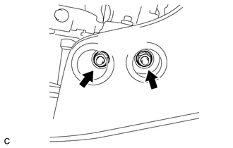
Remove the 2 bolts and No. 1 exhaust pipe support bracket.
-
-
REMOVE FLYWHEEL HOUSING UNDER COVER
-
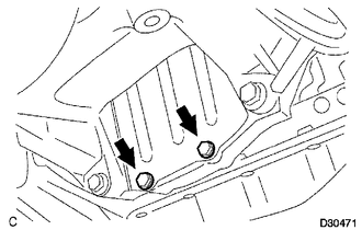
Remove the 2 bolts and flywheel housing under cover.
-
-
REMOVE DRIVE PLATE AND TORQUE CONVERTER ASSEMBLY SETTING BOLT (for 2WD)
-
REMOVE DRIVE PLATE AND TORQUE CONVERTER ASSEMBLY SETTING BOLT (for AWD)
-
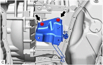
REMOVE ENGINE ASSEMBLY WITH TRANSAXLE
-
Set an engine lifter.
Note
-
Using height adjustment attachments and plate lift attachments, place the engine assembly with transaxle horizontally.
-
Securely support the engine assembly to prevent it from turning upside down until it is secured to an engine stand.
-
To prevent the oil pan from deforming, do not place any attachments under the oil pan of the engine assembly with transaxle.
-
Do not perform any procedure while the engine assembly with transaxle is suspended because doing so may cause the engine assembly with transaxle to drop, resulting in injury. However, the engine assembly with transaxle needs to be suspended when it is installed to or removed from an engine stand.
-
-
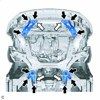
Bolt Nut Remove the 6 bolts, 2 nuts and frame side plate RH and frame side plate LH.
-
Remove the 6 bolts, 2 nuts and front suspension member rear brace RH and front suspension member rear brace LH.
-
Operate the engine lifter and remove the engine assembly with transaxle from the vehicle.
Note
-
Make sure that the engine assembly with transaxle is clear of all wiring and hoses.
-
While lowering the engine assembly with transaxle from the vehicle, do not allow it to contact the vehicle.
-
-
-
INSTALL ENGINE HANGERS
-
*A for Bank 1 *B for Bank 2 *1 No. 1 Engine Hanger (Part No. 12281-31120) *2 No. 2 Engine Hanger (Part No. 12282-31100) *3 Bolt (Part No. 91671-10825) or (Part No. 90119-A0117) Install the No. 1 engine hanger and No. 2 engine hanger with the 4 bolts as shown in the illustration.
- Torque:
- 33 N*m { 337 kgf*cm, 24 ft.*lbf }
-
Attach the engine sling device and hang the engine assembly with transaxle with the chain block.
Note
-
Pay attention to the angle of the sling device as the engine assembly or No. 1 engine hanger and No. 2 engine hanger may be damaged or deformed if the angle is incorrect.
-
Do not perform any procedure while the engine assembly with transaxle is suspended because doing so may cause the engine assembly with transaxle to drop, resulting in injury. However, the engine assembly with transaxle needs to be suspended when it is installed to or removed from an engine stand.
-
-
-
REMOVE V-RIBBED BELT
-
REMOVE COMPRESSOR ASSEMBLY WITH PULLEY
-
REMOVE FRONT NO. 1 STABILIZER BRACKET LH (for AWD)
-
REMOVE FRONT NO. 1 STABILIZER BRACKET RH (for AWD)
Tech Tips
Perform the same procedure as for the LH side.
-
REMOVE FRONT STABILIZER BAR (for AWD)
-
REMOVE STEERING LINK ASSEMBLY (for AWD)
-
REMOVE FRONT FRAME ASSEMBLY
-
Disconnect the 2 clamps.
-
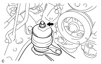
Remove the bolt and disconnect the front engine mounting insulator assembly.
-
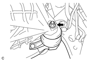
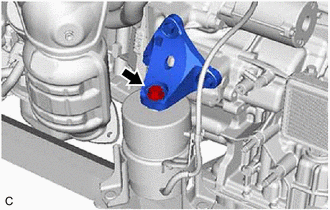
Remove the nut and disconnect the engine mounting insulator LH.
-
Remove the nut and disconnect the engine mounting insulator RH.
-
Remove the 2 bolts and disconnect the rear engine mounting insulator assembly.
-
Remove the front frame assembly.
-
-
REMOVE FRONT ENGINE MOUNTING INSULATOR ASSEMBLY
Tech Tips
Perform this procedure only when replacement of the front engine mounting insulator assembly is necessary.
-
Remove the hole plug from the front frame assembly.
-
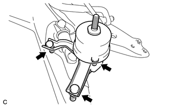
Remove the 3 nuts and front engine mounting insulator assembly.
-
-
REMOVE ENGINE MOUNTING INSULATOR LH
Tech Tips
Perform this procedure only when replacement of the engine mounting insulator LH is necessary.
-
Remove the 2 hole plugs from the front frame assembly.
-
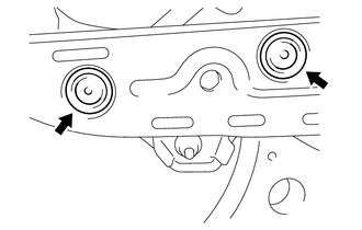
Remove the 3 nuts and engine mounting insulator LH.
-
-
REMOVE ENGINE MOUNTING INSULATOR RH
Tech Tips
Perform this procedure only when replacement of the engine mounting insulator RH is necessary.
-
Remove the 2 hole plugs from the front frame assembly.
-
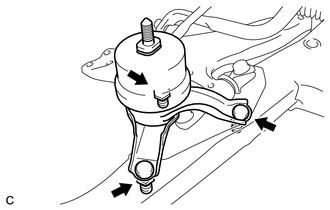
Remove the 3 nuts and engine mounting insulator RH.
-
-
REMOVE REAR ENGINE MOUNTING INSULATOR ASSEMBLY
Tech Tips
Perform this procedure only when replacement of the rear engine mounting insulator assembly is necessary.
-
Remove the 2 hole plugs from the front frame assembly.
-
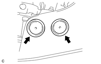
Remove the 2 nuts and rear engine mounting insulator assembly.
-
-
REMOVE MANIFOLD STAY
-
REMOVE ENGINE WIRE
-
Remove the engine wire from the engine assembly with transaxle.
-
-
REMOVE RADIATOR PIPE CLAMP (for 2WD)
-
REMOVE RADIATOR PIPE CLAMP (for AWD)
-
REMOVE TRANSFER STIFFENER PLATE RH (for AWD)
-
REMOVE AUTOMATIC TRANSAXLE ASSEMBLY (for 2WD)
-
REMOVE AUTOMATIC TRANSAXLE ASSEMBLY (for AWD)
-
REMOVE DRIVE PLATE AND RING GEAR SUB-ASSEMBLY
-
INSTALL ENGINE TO ENGINE STAND
-
Install the engine assembly to an engine stand.
Note
-
Pay attention to the angle of the sling device as the engine assembly or No. 1 engine hanger and No. 2 engine hanger may be damaged or deformed if the angle is incorrect.
-
Servicing an engine assembly while it is hanging is dangerous. This can be done only when installing/removing the engine assembly to/from an engine stand.
-
-
-
REMOVE ENGINE HANGERS
-
Remove the 4 bolts, No. 1 engine hanger and No. 2 engine hanger.
-