CAMSHAFT INSTALLATION

CAUTION / NOTICE / HINT
Tech Tips
Perform "Inspection After Repair" after replacing the camshaft, No. 2 camshaft, No. 3 camshaft, No. 4 camshaft, camshaft timing gear assembly or camshaft timing exhaust gear assembly.
PROCEDURE
-
INSTALL NO. 3 CAMSHAFT
-
Apply a light coat of engine oil to the No. 3 camshaft journals and camshaft housing sub-assembly LH.
-
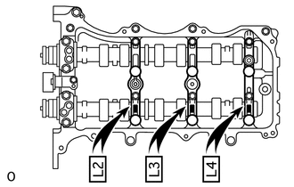
Install the No. 3 camshaft to the camshaft housing sub-assembly LH.
-
-
INSTALL NO. 4 CAMSHAFT
-
Apply a light coat of engine oil to the No. 4 camshaft journals and camshaft housing sub-assembly LH.
-
Install the No. 4 camshaft to the camshaft housing sub-assembly LH.
-
-
INSTALL CAMSHAFT BEARING CAP (for Bank 2)
-
Apply engine oil to the 5 camshaft bearing caps.
-
Confirm the marks and numbers on the camshaft bearing caps and place them in each proper position and direction.
-
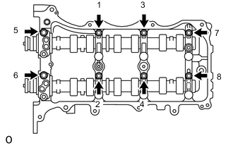
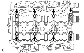
Temporarily tighten the 8 bolts in the order shown in the illustration.
- Torque:
- 10 N*m { 102 kgf*cm, 7 ft.*lbf }
-
-
INSTALL CAMSHAFT HOUSING SUB-ASSEMBLY LH
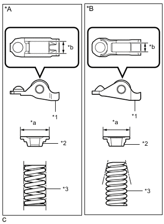
*A Type A *B Type B *1 No. 1 Valve Rocker Arm Sub-assembly *2 Valve Spring Retainer *3 Inner Compression Spring *a Valve Spring Retainer Diameter *b No. 1 Valve Rocker Arm Sub-assembly Roller Width Tech Tips
Type A and Type B can be distinguished by the shape of the compression spring.
Type No. 1 Valve Rocker Arm Sub-assembly Roller Width Valve Spring Retainer Diameter Inner Compression Spring Shape A 10.7 mm (0.421 in.) 23.4 mm (0.921 in.) Straight B 8.0 mm (0.315 in.) 18.9 mm (0.744 in.) Taper
-
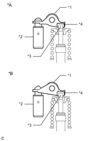
*A Type A *B Type B *1 No. 1 Valve Rocker Arm Sub-assembly *2 Valve Lash Adjuster Assembly *3 Valve Stem *4 Valve Stem Cap Make sure that the No. 1 valve rocker arm sub-assemblies are installed as shown in the illustration.
-
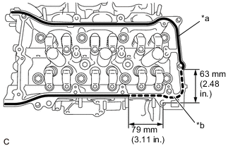
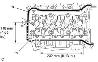
*a Continuous Line Area (Seal Packing) *b Dashed line area (Seal Packing) Apply seal packing in a continuous line as shown in the illustration.
Seal Packing Toyota Genuine Seal Packing Black, Three Bond 1207B or equivalent Seal Packing Application Chart Area Seal Packing Diameter Continuous Line Area 2.7 to 4.5 mm (0.107 to 0.177 in.) Dashed Line Area 3.5 to 4.5 mm (0.138 to 0.177 in.) Note
-
Remove any oil from the contact surface.
-
Install the camshaft housing sub-assembly LH and tighten the bolts within 3 minutes.
-
Do not start the engine for at least 2 hours after installation.
-
-
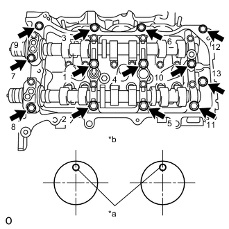
*a Knock Pin *b Front View Install the camshaft housing sub-assembly LH and tighten the 13 bolts in the order shown in the illustration.
- Torque:
- 28 N*m { 286 kgf*cm, 21 ft.*lbf }
Note
-
When installing the camshaft housing sub-assembly LH, correctly position the camshafts as shown in the illustration. Failure to do so may result in damage due to contact between the pistons and valves. If a camshaft is rotated, valve contact with a piston at TDC may occur.
-
If any of the bolts are loosened during installation, remove the camshaft housing sub-assembly LH, clean the installation surfaces, and reapply seal packing.
-
If the camshaft housing sub-assembly LH is removed because any of the bolts are loosened during installation, make sure that the previously applied seal packing does not enter any oil passages.
-
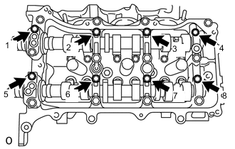
Tighten the 8 bolts in the order shown in the illustration.
- Torque:
- 16 N*m { 163 kgf*cm, 12 ft.*lbf }
-
-
INSTALL CAMSHAFT
-
Apply a light coat of engine oil to the camshaft journals and camshaft housing sub-assembly RH.
-
Install the camshaft to the camshaft housing sub-assembly RH.
-
-
INSTALL NO. 2 CAMSHAFT
-
Apply a light coat of engine oil to the No. 2 camshaft journals and camshaft housing sub-assembly RH.
-
Install the No. 2 camshaft to the camshaft housing sub-assembly RH.
-
-
INSTALL CAMSHAFT BEARING CAP (for Bank 1)
-
Apply engine oil to the camshaft bearing caps.
-
Confirm the marks and numbers on the camshaft bearing caps and place them in their proper positions and directions.
-
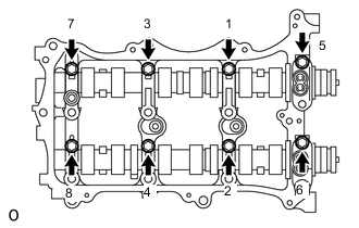
Temporarily tighten the 8 bolts in the order shown in the illustration.
- Torque:
- 10 N*m { 102 kgf*cm, 7 ft.*lbf }
-
-
INSTALL CAMSHAFT HOUSING SUB-ASSEMBLY RH
*A Type A *B Type B *1 No. 1 Valve Rocker Arm Sub-assembly *2 Valve Spring Retainer *3 Inner Compression Spring *a Valve Spring Retainer Diameter *b No. 1 Valve Rocker Arm Sub-assembly Roller Width Tech Tips
Type A and Type B can be distinguished by the shape of the compression spring.
Type No. 1 Valve Rocker Arm Sub-assembly Roller Width Valve Spring Retainer Diameter Inner Compression Spring Shape A 10.7 mm (0.421 in.) 23.4 mm (0.921 in.) Straight B 8.0 mm (0.315 in.) 18.9 mm (0.744 in.) Taper
-
*A Type A *B Type B *1 No. 1 Valve Rocker Arm Sub-assembly *2 Valve Lash Adjuster Assembly *3 Valve Stem *4 Valve Stem Cap Make sure that the No. 1 valve rocker arm sub-assemblies are installed as shown in the illustration.
-
*a Continuous Line Area (Seal Packing) *b Dashed line area (Seal Packing) Apply seal packing in a continuous line as shown in the illustration.
Seal Packing Toyota Genuine Seal Packing Black, Three Bond 1207B or equivalent Seal Packing Application Chart Area Seal Packing Diameter Continuous Line Area 2.7 to 4.5 mm (0.107 to 0.177 in.) Dashed Line Area 3.5 to 4.5 mm (0.138 to 0.177 in.) Note
-
Remove any oil from the contact surface.
-
Install the camshaft housing sub-assembly RH and tighten the bolts within 3 minutes.
-
Do not start the engine for at least 2 hours after installation.
-
-
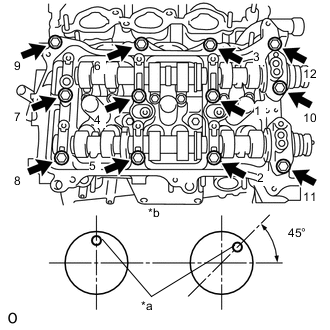
*a Knock Pin *b Front View Install the camshaft housing sub-assembly RH and tighten the 12 bolts in the order shown in the illustration.
- Torque:
- 28 N*m { 286 kgf*cm, 21 ft.*lbf }
Note
-
When installing the camshaft housing sub-assembly RH, correctly position the camshafts as shown in the illustration.
Failure to do so may result in damage due to contact between the pistons and valves. If a camshaft is rotated, valve contact with a piston at TDC may occur.
-
If any of the bolts are loosened during installation, remove the camshaft housing sub-assembly RH, clean the installation surfaces, and reapply seal packing.
-
If the camshaft housing sub-assembly RH is removed because any of the bolts are loosened during installation, make sure that the previously applied seal packing does not enter any oil passages.
-
Tighten the 8 bolts in the order shown in the illustration.
- Torque:
- 16 N*m { 163 kgf*cm, 12 ft.*lbf }
-
-
INSTALL NO. 3 CHAIN TENSIONER ASSEMBLY
-
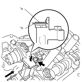
*a Plunger *b Pin *c Push Install the No. 3 chain tensioner assembly with the bolt.
- Torque:
- 21 N*m { 214 kgf*cm, 15 ft.*lbf }
-
While pushing down the No. 3 chain tensioner assembly, insert a 1.0 mm (0.0394 in.) diameter pin into the hole to secure it.
-
-
INSTALL CAMSHAFT TIMING GEAR ASSEMBLY, CAMSHAFT TIMING EXHAUST GEAR ASSEMBLY AND NO. 2 CHAIN SUB-ASSEMBLY (for Bank 2)
-
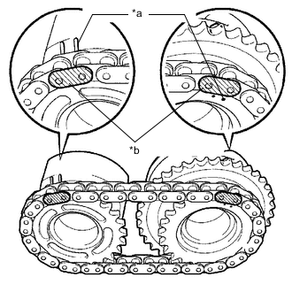
*a Timing Mark *b Mark Plate Align the mark plates (yellow) with the timing marks of the camshaft timing gear assembly as shown in the illustration.
-
Apply a light coat of engine oil to the bolt threads and bolt-seating surface.
-
Align the knock pin of the No. 3 camshaft and No. 4 camshaft with the pin hole of the camshaft timing gear assembly and camshaft timing exhaust gear assembly. Install the camshaft timing gear assembly and camshaft timing exhaust gear assembly with the No. 2 chain sub-assembly installed.
-
Using SST to hold the hexagonal portion of each camshaft, tighten the bolts of the camshaft timing gear assembly and the camshaft timing exhaust gear assembly.
- SST
- 09922-10010
- Torque:
- 100 N*m { 1020 kgf*cm, 74 ft.*lbf }
-
Remove the pin from the No. 3 chain tensioner assembly.
Tech Tips
Perform "Inspection After Repair" after replacing the camshaft timing gear assembly or camshaft timing exhaust gear assembly.
-
-
INSTALL NO. 2 CHAIN TENSIONER ASSEMBLY
-
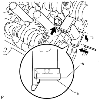
*a Plunger *b Pin *c Push Install the No. 2 chain tensioner assembly with the bolt.
- Torque:
- 21 N*m { 214 kgf*cm, 15 ft.*lbf }
-
While pushing up the No. 2 chain tensioner assembly, insert a 1.0 mm (0.0394 in.) diameter pin into the hole to secure it.
-
-
INSTALL CAMSHAFT TIMING GEAR ASSEMBLY, CAMSHAFT TIMING EXHAUST GEAR ASSEMBLY AND NO. 2 CHAIN SUB-ASSEMBLY (for Bank 1)
-
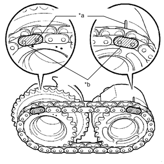
*a Timing Mark *b Mark Plate Align the mark plates (yellow) with the timing marks of the camshaft timing gear assembly as shown in the illustration.
-
Apply a light coat of engine oil to the bolt threads and bolt-seating surface.
-
Align the knock pin of the camshaft and No. 2 camshaft with the pin hole of the camshaft timing gear assembly and camshaft timing exhaust gear assembly. Install the camshaft timing gear assembly and camshaft timing exhaust gear assembly with the No. 2 chain sub-assembly installed.
-
Using SST to hold the hexagonal portion of each camshaft, tighten the bolts of the camshaft timing gear assembly and the camshaft timing exhaust gear assembly.
- SST
- 09922-10010
- Torque:
- 100 N*m { 1020 kgf*cm, 74 ft.*lbf }
-
Remove the pin from the No. 2 chain tensioner assembly.
Tech Tips
Perform "Inspection After Repair" after replacing the camshaft timing gear assembly or camshaft timing exhaust gear assembly.
-
-
INSTALL IDLE SPROCKET ASSEMBLY
-
INSTALL CHAIN SUB-ASSEMBLY
-
INSTALL CHAIN TENSIONER SLIPPER
-
INSTALL NO. 1 CHAIN TENSIONER ASSEMBLY
-
INSPECT VALVE TIMING
-
INSTALL TIMING CHAIN CASE OIL SEAL
-
INSTALL TIMING CHAIN COVER SUB-ASSEMBLY
-
INSTALL OIL PAN SUB-ASSEMBLY
-
Install 2 new O-rings.
-
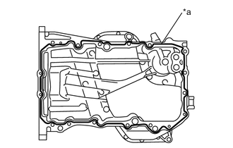
*a Seal Packing Apply seal packing in a continuous line as shown in the illustration.
Seal Packing Toyota Genuine Seal Packing Black, Three Bond 1207B or equivalent Seal Packing Diameter 2.5 to 3.5 mm (0.0985 to 0.1377 in.) Note
-
Remove any oil from the contact surfaces.
-
Install the oil pan sub-assembly within 3 minutes of applying seal packing.
-
Do not start the engine for at least 2 hours after installation.
-
-
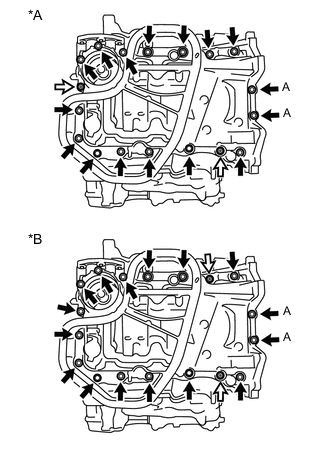
*A Type A *B Type B 
Bolt 
Nut Install the oil pan sub-assembly with the 16 bolts and 2 nuts.
- Torque:
- Bolt (A)
- 10 N*m { 102 kgf*cm, 7 ft.*lbf }
- Except Bolt (A)
- 21 N*m { 214 kgf*cm, 15 ft.*lbf }
-
-
INSTALL OIL STRAINER SUB-ASSEMBLY
-
INSTALL NO. 2 OIL PAN SUB-ASSEMBLY
-
INSTALL CYLINDER HEAD COVER SUB-ASSEMBLY
-
INSTALL CYLINDER HEAD COVER SUB-ASSEMBLY LH
-
INSTALL WATER INLET HOUSING
-
INSTALL NO. 1 FRONT ENGINE MOUNTING BRACKET LH
-
INSTALL NO. 1 OIL COOLER BRACKET
-
INSTALL OIL COOLER ASSEMBLY
-
INSTALL CRANKSHAFT PULLEY
-
INSTALL NO. 1 OIL PIPE
-
INSTALL OIL PIPE
-
INSTALL CRANKSHAFT POSITION SENSOR
-
INSTALL NO. 1 VACUUM SWITCHING VALVE
-
INSTALL WATER PUMP PULLEY
-
INSTALL NO. 2 IDLER PULLEY SUB-ASSEMBLY
-
INSTALL NO. 2 TIMING GEAR COVER
-
INSTALL ENGINE OIL LEVEL DIPSTICK GUIDE
-
INSTALL V-RIBBED BELT TENSIONER ASSEMBLY
-
INSTALL GENERATOR ASSEMBLY
-
INSTALL ENGINE MOUNTING BRACKET RH
-
INSTALL EXHAUST MANIFOLD SUB-ASSEMBLY LH (TWC: Front Catalyst)
-
INSTALL NO. 2 EXHAUST MANIFOLD HEAT INSULATOR
-
INSTALL NO. 2 MANIFOLD STAY
-
INSTALL NO. 2 ENGINE OIL LEVEL DIPSTICK GUIDE
-
INSTALL EXHAUST MANIFOLD SUB-ASSEMBLY RH (TWC: Front Catalyst)
-
INSTALL INTAKE MANIFOLD
-
INSTALL IGNITION COIL ASSEMBLY
-
INSTALL ENGINE HANGERS
-
REMOVE ENGINE FROM ENGINE STAND