CAMSHAFT REMOVAL

PROCEDURE
-
INSTALL ENGINE TO ENGINE STAND
-
REMOVE ENGINE HANGERS
-
REMOVE IGNITION COIL ASSEMBLY
-
REMOVE INTAKE MANIFOLD
-
REMOVE EXHAUST MANIFOLD SUB-ASSEMBLY RH (TWC: Front Catalyst)
-
REMOVE NO. 2 ENGINE OIL LEVEL DIPSTICK GUIDE
-
REMOVE NO. 2 MANIFOLD STAY
-
REMOVE NO. 2 EXHAUST MANIFOLD HEAT INSULATOR
-
REMOVE EXHAUST MANIFOLD SUB-ASSEMBLY LH (TWC: Front Catalyst)
-
REMOVE ENGINE MOUNTING BRACKET RH
-
REMOVE GENERATOR ASSEMBLY
-
REMOVE V-RIBBED BELT TENSIONER ASSEMBLY
-
REMOVE ENGINE OIL LEVEL DIPSTICK GUIDE
-
REMOVE NO. 2 TIMING GEAR COVER
-
REMOVE WATER PUMP PULLEY
-
REMOVE NO. 2 IDLER PULLEY SUB-ASSEMBLY
-
REMOVE NO. 1 VACUUM SWITCHING VALVE
-
REMOVE CRANKSHAFT POSITION SENSOR
-
REMOVE NO. 1 OIL PIPE
-
REMOVE OIL PIPE
-
REMOVE CRANKSHAFT PULLEY
-
REMOVE OIL COOLER ASSEMBLY
-
REMOVE NO. 1 OIL COOLER BRACKET
-
REMOVE NO. 1 FRONT ENGINE MOUNTING BRACKET LH
-
REMOVE WATER INLET HOUSING
-
REMOVE CYLINDER HEAD COVER SUB-ASSEMBLY
-
REMOVE CYLINDER HEAD COVER SUB-ASSEMBLY LH
-
REMOVE NO. 2 OIL PAN SUB-ASSEMBLY
-
REMOVE OIL STRAINER SUB-ASSEMBLY
-
REMOVE OIL PAN SUB-ASSEMBLY
-
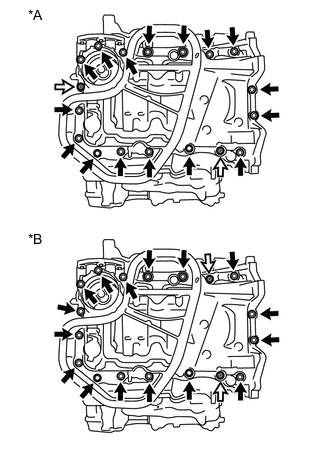
*A Type A *B Type B 
Bolt 
Nut Remove the 16 bolts and 2 nuts.
Tech Tips
Be sure to clean the bolts and stud bolts and check the threads for cracks or other damage.
-
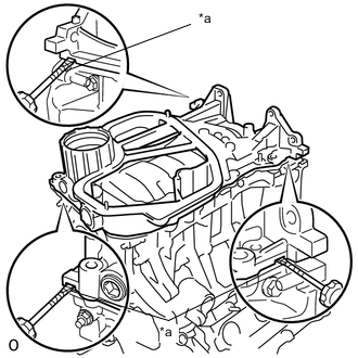
*a Protective Tape Remove the oil pan sub-assembly by prying between the oil pan sub-assembly and cylinder block sub-assembly with a screwdriver.
Note
Be careful not to damage the contact surfaces of the cylinder block sub-assembly and oil pan sub-assembly.
Tech Tips
Tape the screwdriver tip before use.
-
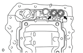
Remove the 2 O-rings.
-
-
REMOVE TIMING CHAIN COVER SUB-ASSEMBLY
-
REMOVE TIMING CHAIN CASE OIL SEAL
-
SET NO. 1 CYLINDER TO TDC/COMPRESSION
-
REMOVE NO. 1 CHAIN TENSIONER ASSEMBLY
-
REMOVE CHAIN TENSIONER SLIPPER
-
REMOVE CHAIN SUB-ASSEMBLY
-
REMOVE IDLE SPROCKET ASSEMBLY
-
REMOVE CAMSHAFT TIMING GEAR ASSEMBLY, CAMSHAFT TIMING EXHAUST GEAR ASSEMBLY AND NO. 2 CHAIN SUB-ASSEMBLY (for Bank 1)
-
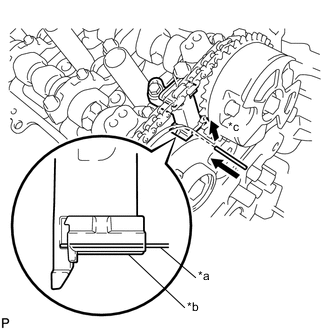
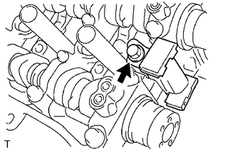
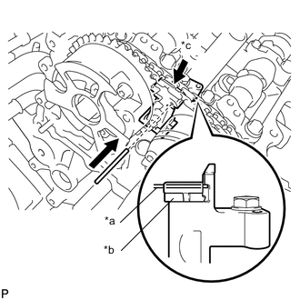
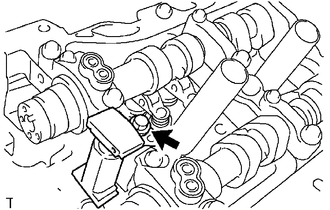
*a Pin *b Plunger *c Push While raising the No. 2 chain tensioner assembly, insert a 1.0 mm (0.0394 in.) diameter pin into the hole to secure the No. 2 chain tensioner assembly.
-
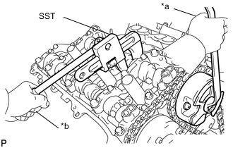
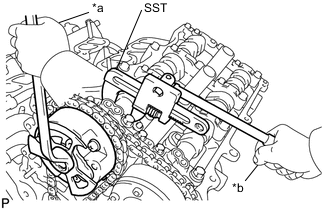
*a Turn *b Hold Using SST to hold the hexagonal portion of each camshaft, loosen the bolts of the camshaft timing gear assembly and the camshaft timing exhaust gear assembly.
- SST
- 09922-10010
Note
-
Be careful not to damage the cylinder head sub-assembly RH with SST.
-
Do not loosen the other bolts. If any of the bolts is loosened, replace the camshaft timing gear assembly and/or the camshaft timing exhaust gear assembly with a new one.
-
Remove the 2 bolts, camshaft timing gear assembly and camshaft timing exhaust gear assembly together with the No. 2 chain sub-assembly.
-
-
REMOVE NO. 2 CHAIN TENSIONER ASSEMBLY
-
Remove the bolt and No. 2 chain tensioner assembly.
-
-
REMOVE CAMSHAFT BEARING CAP (for Bank 1)
-
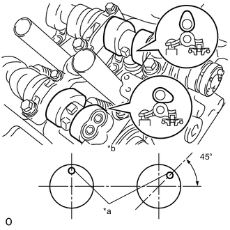
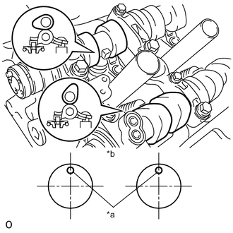
*a Knock Pin *b Front View Check that the camshaft and No. 2 camshaft are positioned as shown in the illustration.
-
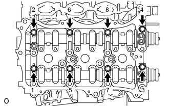
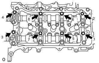
Uniformly loosen and remove the 8 bolts in several steps in the order shown in the illustration.
-
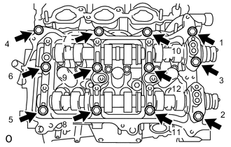
Uniformly loosen and remove the 12 bolts in several steps in the order shown in the illustration.
Note
Uniformly loosen the bolts while keeping the camshaft and No. 2 camshaft level.
-
Remove the 5 camshaft bearing caps.
-
-
REMOVE CAMSHAFT
-
Remove the camshaft.
-
-
REMOVE NO. 2 CAMSHAFT
-
Remove the No. 2 camshaft.
-
-
REMOVE CAMSHAFT HOUSING SUB-ASSEMBLY RH
-
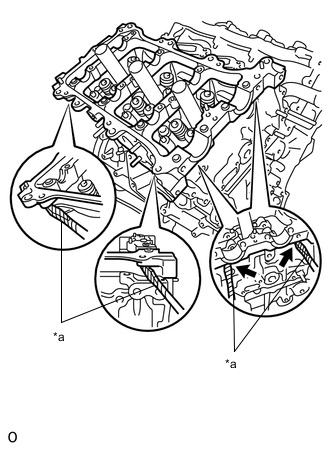
*a Protective Tape Remove the camshaft housing sub-assembly RH by prying between the cylinder head sub-assembly RH and camshaft housing sub-assembly RH with a screwdriver.
Note
Be careful not to damage the contact surfaces of the cylinder head sub-assembly RH and camshaft housing sub-assembly RH.
Tech Tips
Tape the screwdriver tip before use.
-
-
REMOVE CAMSHAFT TIMING GEAR ASSEMBLY, CAMSHAFT TIMING EXHAUST GEAR ASSEMBLY AND NO. 2 CHAIN SUB-ASSEMBLY (for Bank 2)
-
*a Pin *b Plunger *c Push While pushing down the No. 3 chain tensioner assembly, insert a 1.0 mm (0.0394 in.) diameter pin into the hole to secure the No. 3 chain tensioner assembly.
-
*a Turn *b Hold Using SST to hold the hexagonal portion of each camshaft, loosen the bolts of the camshaft timing gear assembly and the camshaft timing exhaust gear assembly.
- SST
- 09922-10010
Note
-
Be careful not to damage the cylinder head sub-assembly LH with SST.
-
Do not loosen the other bolts. If any of the bolts is loosened, replace the camshaft timing gear assembly and/or the camshaft timing exhaust gear assembly with a new one.
-
Remove the 2 bolts, camshaft timing gear assembly and camshaft timing exhaust gear assembly together with the No. 2 chain sub-assembly.
-
-
REMOVE NO. 3 CHAIN TENSIONER ASSEMBLY
-
Remove the bolt and No. 3 chain tensioner assembly.
-
-
REMOVE CAMSHAFT BEARING CAP (for Bank 2)
-
*a Knock Pin *b Front View Check that the No. 3 camshaft and No. 4 camshaft are positioned as shown in the illustration.
-
Uniformly loosen and remove the 8 bolts in several steps in the order shown in the illustration.
-
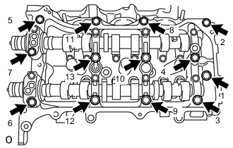
Uniformly loosen and remove the 13 bolts in several steps in the order shown in the illustration.
Note
Uniformly loosen the bolts while keeping the No. 3 camshaft and No. 4 camshaft level.
-
Remove the 5 camshaft bearing caps.
-
-
REMOVE NO. 3 CAMSHAFT
-
Remove the No. 3 camshaft.
-
-
REMOVE NO. 4 CAMSHAFT
-
Remove the No. 4 camshaft.
-
-
REMOVE CAMSHAFT HOUSING SUB-ASSEMBLY LH
-
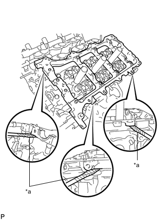
*a Protective Tape Remove the camshaft housing sub-assembly LH by prying between the cylinder head sub-assembly LH and camshaft housing sub-assembly LH with a screwdriver.
Note
Be careful not to damage the contact surfaces of the cylinder head sub-assembly LH and camshaft housing sub-assembly LH.
Tech Tips
Tape the screwdriver tip before use.
-