CAMSHAFT OIL CONTROL VALVE(for Intake Side of Bank 2) REMOVAL
PROCEDURE
-
REMOVE FRONT WHEEL RH
-
REMOVE FRONT FENDER APRON SEAL RH
-
REMOVE V-BANK COVER SUB-ASSEMBLY
-
REMOVE WINDSHIELD WIPER MOTOR AND LINK ASSEMBLY (for RHD)
-
REMOVE OUTER COWL TOP PANEL SUB-ASSEMBLY (for RHD)
-
SEPARATE BRAKE MASTER CYLINDER RESERVOIR ASSEMBLY (for RHD)
-
REMOVE RESERVOIR BRACKET (for RHD)
-
REMOVE NO. 2 ENGINE MOUNTING STAY RH
-
REMOVE ENGINE MOVING CONTROL ROD BRACKET
-
REMOVE CAMSHAFT TIMING OIL CONTROL SOLENOID ASSEMBLY (for Intake Side of Bank 2)
-
SET NO. 1 CYLINDER TO TDC/COMPRESSION
-
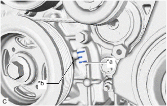
*a Timing Mark *b Timing Mark (Cutout) Turn the crankshaft pulley clockwise until its timing mark (cutout) is aligned with the timing mark on the timing chain cover assembly as shown in the illustration.
-
Check that the cutout of the camshaft timing gear assembly is at the top.
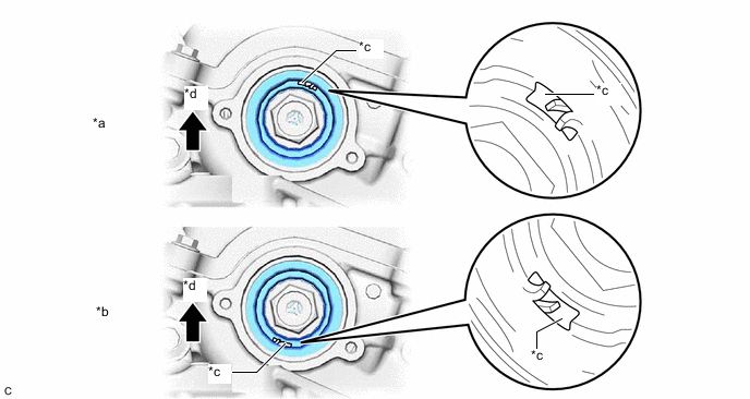
*a Correct *b Incorrect *c Cutout *d Up Tech Tips
If the cutout of the camshaft timing gear assembly (for intake side) is not at the top, turn the crankshaft 360° clockwise and align the timing mark (cutout) of the crankshaft pulley with the timing mark on the timing chain cover assembly again.
-
-
REMOVE CAMSHAFT TIMING GEAR BOLT
-
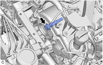
While holding the crankshaft pulley, remove the camshaft timing gear bolt.
Note
-
If the camshaft timing gear bolt has been struck or dropped, replace it.
-
Do not turn the crankshaft pulley after removing the camshaft timing gear bolt.
-
-