INTAKE MANIFOLD REMOVAL
PROCEDURE
-
PRECAUTION
Note
After turning the ignition switch off, waiting time may be required before disconnecting the cable from the negative (-) battery terminal. Therefore, make sure to read the disconnecting the cable from the negative (-) battery terminal notice before proceeding with work.
-
DISCHARGE FUEL SYSTEM PRESSURE
-
DISCONNECT CABLE FROM NEGATIVE BATTERY TERMINAL
Note
When disconnecting the cable, some systems need to be initialized after the cable is reconnected.
-
REMOVE WINDSHIELD WIPER MOTOR AND LINK ASSEMBLY
-
REMOVE OUTER COWL TOP PANEL SUB-ASSEMBLY (for LHD)
-
REMOVE OUTER COWL TOP PANEL SUB-ASSEMBLY (for RHD)
-
REMOVE THROTTLE BODY WITH MOTOR ASSEMBLY
-
REMOVE INTAKE AIR SURGE TANK ASSEMBLY
-
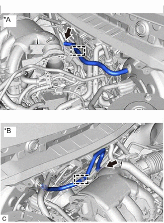
*A for LHD *B for RHD Slide the clip and disconnect the union to check valve hose from the intake air surge tank assembly.
-
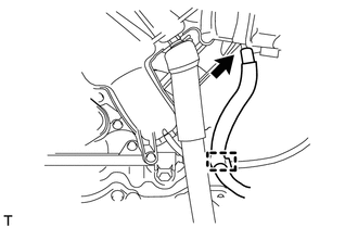
Disconnect the union to check valve hose from the hose clamp.
-
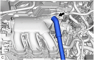
Disconnect the fuel vapor feed hose from the intake air surge tank assembly.
-
Disconnect the fuel vapor feed hose from the hose clamp.
-
Slide the clip and disconnect the ventilation hose from the intake air surge tank assembly.
-
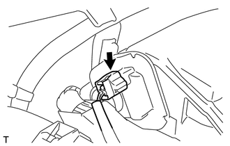
Disconnect the intake air control valve (for ACIS) connector.
-
Remove the bolt and separate the throttle body bracket from the intake air surge tank assembly.
-
Remove the bolt and separate the No. 1 surge tank stay from the intake air surge tank assembly.
-

Bolt 
Nut Remove the 2 nuts from the intake air surge tank assembly.
-
Using a 5 mm hexagon socket wrench, remove the 4 bolts and intake air surge tank assembly from the intake manifold.
-
Remove the 3 intake air surge tank gaskets from the intake manifold.
-
-
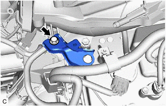
REMOVE NO. 2 ENGINE MOUNTING STAY RH (for Engine Mounting stay Side)
-
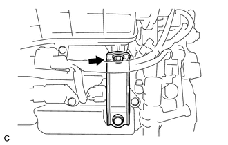
REMOVE NO. 2 ENGINE MOUNTING STAY RH (for Intake Manifold Side)
-
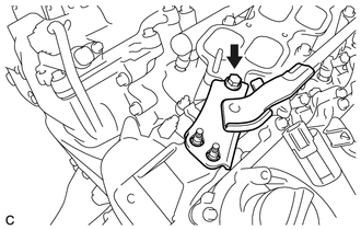
Remove the bolt and No. 2 engine mounting stay RH from the intake manifold.
-
-
REMOVE FUEL HOSE PROTECTOR
-
DISCONNECT FUEL TUBE SUB-ASSEMBLY
-
REMOVE FUEL DELIVERY PIPE SUB-ASSEMBLY
-
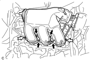
REMOVE INTAKE MANIFOLD
-
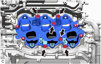
Bolt Nut Remove the 6 bolts, 4 nuts and intake manifold from the cylinder head sub-assembly.
-
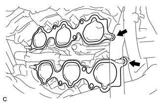
Remove the intake manifold to head gasket from each cylinder head sub-assembly.
-
-
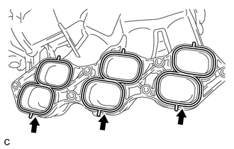
REMOVE STUD BOLT
Tech Tips
If a stud bolt is deformed or the threads are damaged, replace it.
-
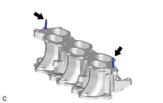
Using an E6 "TORX" socket wrench, remove the 2 stud bolts from the intake manifold.
-