EXHAUST MANIFOLD INSTALLATION
PROCEDURE
-
INSTALL NO. 1 MANIFOLD CONVERTER INSULATOR
-
Install the No. 1 manifold converter insulator to the exhaust manifold converter sub-assembly (TWC: Front Catalyst) with the 4 bolts.
- Torque:
- 13.5 N*m { 138 kgf*cm, 10 ft.*lbf }
-
-
INSTALL NO. 2 EXHAUST MANIFOLD HEAT INSULATOR
-
Install the No. 2 exhaust manifold heat insulator to the exhaust manifold converter sub-assembly (TWC: Front Catalyst) with the 2 bolts.
- Torque:
- 13.5 N*m { 138 kgf*cm, 10 ft.*lbf }
-
-
INSTALL EXHAUST MANIFOLD CONVERTER SUB-ASSEMBLY (TWC: Front Catalyst)
-
Install a new exhaust manifold to head gasket to the cylinder head sub-assembly.
-
Temporarily install the exhaust manifold converter sub-assembly (TWC: Front Catalyst) with the 5 nuts.
-
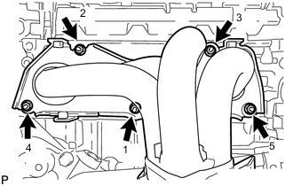
Tighten the 5 nuts in the order shown in the illustration.
- Torque:
- 35 N*m { 357 kgf*cm, 26 ft.*lbf }
-
-
INSTALL AIR FUEL RATIO SENSOR
-
INSTALL NO. 1 EXHAUST MANIFOLD HEAT INSULATOR
-
Install the No. 1 exhaust manifold heat insulator to the exhaust manifold converter sub-assembly (TWC: Front Catalyst) with the 4 bolts.
- Torque:
- 12 N*m { 122 kgf*cm, 9 ft.*lbf }
-
-
INSTALL NO. 2 MANIFOLD STAY
-
Install the No. 2 manifold stay to the exhaust manifold converter sub-assembly (TWC: Front Catalyst) and stiffening crankcase assembly with the bolt and nut.
- Torque:
- 43 N*m { 438 kgf*cm, 32 ft.*lbf }
-
-
INSTALL MANIFOLD STAY
-
Install the manifold stay to the exhaust manifold converter sub-assembly (TWC: Front Catalyst) and stiffening crankcase assembly with the bolt and nut.
- Torque:
- 43 N*m { 438 kgf*cm, 32 ft.*lbf }
-
-
INSTALL FRONT EXHAUST PIPE ASSEMBLY
-
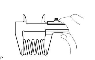
Using a vernier caliper, measure the free length of the 2 compression springs.
Minimum 41.5 mm (1.63 in.) If the free length is less than minimum, replace the compression spring.
-
Temporarily install a new gasket to the exhaust manifold converter sub-assembly (TWC: Front Catalyst).
-
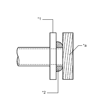
*1 Exhaust Manifold Converter Sub-assembly (TWC: Front Catalyst) *2 Gasket *a Wooden Block Using a plastic hammer and wooden block, tap in the gasket until its surface is flush with the exhaust manifold converter sub-assembly (TWC: Front Catalyst).
Note
-
Be sure to install the gasket in the correct direction.
-
Do not reuse the gasket.
-
Do not damage the gasket.
-
Do not push in the gasket by using the exhaust pipe when connecting it.
-
-
Install a new gasket to the front exhaust pipe assembly.
-
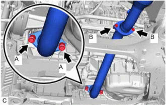
Install the front exhaust pipe assembly with the 2 compression springs and 4 bolts.
- Torque:
- Bolt (A)
- 43 N*m { 438 kgf*cm, 32 ft.*lbf }
- Bolt (B)
- 56 N*m { 571 kgf*cm, 41 ft.*lbf }
Tech Tips
After installation, check that the space between the flanges of the exhaust manifold converter sub-assembly (TWC: Front Catalyst) and front exhaust pipe assembly is consistent front-to-rear and left-to-right.
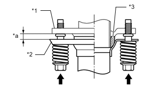
*1 Exhaust Manifold Converter Sub-assembly (TWC: Front Catalyst) *2 Front Exhaust Pipe Assembly *3 Gasket *a Space between Flanges: 8.5 mm (0.335 in.)
-
-
INSTALL FRONT FLOOR COVER LH
-
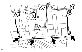

Bolt 
Screw Connect the 2 clips (B) to install the front floor cover LH.
-
Install the clip (A), 2 screws and 4 bolts to the front floor cover LH.
-
-
INSTALL NO. 2 ENGINE UNDER COVER
-
INSTALL NO. 1 ENGINE UNDER COVER
-
INSPECT FOR EXHAUST GAS LEAK