PURGE VALVE INSTALLATION
PROCEDURE
-
INSTALL PURGE VALVE (PURGE VSV)
-
Install the purge valve (purge VSV) to the cylinder head cover sub-assembly LH with the bolt.
- Torque:
- 10 N*m { 102 kgf*cm, 7 ft.*lbf }
-
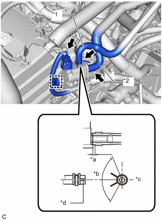
*1 Fuel Vapor Feed Hose Assembly *2 No. 1 Fuel Vapor Feed Hose *a 2 to 7 mm (0.0787 to 0.276 in.) *b 120° *c RH *d Paint Mark Connect the No. 1 fuel vapor feed hose to the purge valve (purge VSV).
-
Connect the fuel vapor feed hose assembly to the purge valve (purge VSV) and slide the clip to secure it.
Tech Tips
Engage the clip within the area shown in the illustration.
-
Engage the wire harness clamp to the purge valve (purge VSV).
-
Connect the purge valve (purge VSV) connector.
-
-
INSTALL V-BANK COVER SUB-ASSEMBLY