WATER PUMP INSTALLATION

PROCEDURE
-
INSTALL ENGINE WATER PUMP ASSEMBLY
-
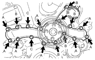
Install a new water pump gasket and engine water pump assembly together with the water pump pulley with the 16 bolts.
- Torque:
- Bolt (A)
- 21 N*m { 214 kgf*cm, 15 ft.*lbf }
- Bolt (B) and (C)
- 11 N*m { 112 kgf*cm, 8 ft.*lbf }
Note
-
Make sure that there is no oil on the threads of the bolts (A).
-
Be sure to replace the 2 bolts (C) with new ones or reuse them after applying adhesive.
-
Do not start the engine within 1 hour of installation.
Adhesive Toyota Genuine Adhesive 1344, Three Bond 1344 or equivalent
-
-
INSTALL WATER PUMP PULLEY
-
Temporarily install the water pump pulley with the 4 bolts.
-
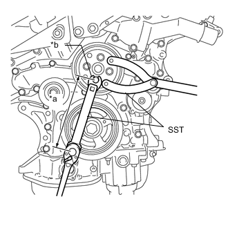
*a Length of SST and Union Nut Wrench 170 mm (6.69 in.) *b 12 mm Union Nut Wrench Using SST, hold the water pump pulley.
- SST
- 09960-10010 ( 09962-01000, 09963-00700 )
-
Using SST and 12 mm union nut wrench, tighten the 4 bolts.
- SST
- 09961-00950
- Torque:
- without SST [Torque (N*m (kgf*cm, ft.*lbf))]
- 21 N*m { 214 kgf*cm, 15 ft.*lbf }
- with SST [Reading of Torque wrench (N*m (kgf*cm, ft.*lbf))]
- 11 N*m { 112 kgf*cm, 8 ft.*lbf }
Tech Tips
-
This torque value is effective when SST is parallel to the torque wrench.
-
The "with SST" torque value is effective when using SST and union nut wrench with a fulcrum length of 170 mm (6.69in.).
-
The "with SST" torque value is effective when using a torque wrench with a fulcrum length of 180 mm (7.09 in.).
-
If using a torque wrench with a different length, or connecting the torque wrench, SST and union nut wrench at an angle, refer to the alternate torque values.
-
-
INSTALL WATER INLET HOUSING
-
Install 2 new O-rings.
-
Install the water inlet housing with the 2 bolts and nut.
- Torque:
- 10 N*m { 102 kgf*cm, 7 ft.*lbf }
Note
Be careful not to allow the O-ring to get caught between the parts.
-
Connect the water by-pass hose and slide the clip to secure it.
-
-
INSTALL V-RIBBED BELT TENSIONER PULLEY
-
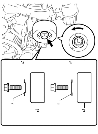
*1 Dust Shield *2 V-ribbed Belt Tensioner Pulley *a Correct *b Incorrect Install the V-ribbed belt tensioner pulley and dust shield with the bolt.
Note
-
Be careful when tightening the bolt because its thread is left-handed.
-
Install the dust shield in the direction shown in the illustration. Failure to do so may cause looseness.
-
Make sure to use the removed bolt. (Do not use another bolt even if it is the same size.)
- Torque:
- 48 N*m { 489 kgf*cm, 35 ft.*lbf }
-
-
Install a 5 mm bi-hexagon wrench.
-
-
INSTALL NO. 2 IDLER PULLEY SUB-ASSEMBLY
-
INSTALL FRONT NO. 1 ENGINE MOUNTING BRACKET LH
-
Temporarily install the front No. 1 engine mounting bracket LH with the 6 bolts.
-
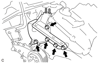
Fully tighten the 5 bolts.
- Torque:
- 54 N*m { 551 kgf*cm, 40 ft.*lbf }
-
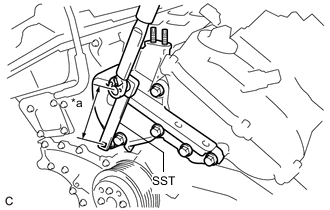
*a Length of SST 150 mm (5.91 in.) Using SST, fully tighten the bolt.
- SST
- 09961-00950
- Torque:
- without SST [Torque (N*m (kgf*cm, ft.*lbf))]
- 54 N*m { 551 kgf*cm, 40 ft.*lbf }
- with SST [Reading of Torque wrench (N*m (kgf*cm, ft.*lbf))]
- 34 N*m { 347 kgf*cm, 25 ft.*lbf }
Tech Tips
-
This torque value is effective when SST is parallel to the torque wrench.
-
The "with SST" torque value is effective when using SST with a fulcrum length of 150 mm (5.91 in.).
-
The "with SST" torque value is effective when using a torque wrench with a fulcrum length of 260 mm (10.2 in.).
-
If using a torque wrench with a different length, or connecting the torque wrench and SST at an angle, refer to the alternate torque values.
-
Lower the engine, and remove the jack.
-
-
INSTALL ENGINE MOUNTING INSULATOR RH
-
Install the engine mounting insulator RH with the 3 nuts.
- Torque:
- 99 N*m { 1010 kgf*cm, 73 ft.*lbf }
-
Install the 2 hole plugs.
-
-
INSTALL FRONT ENGINE MOUNTING INSULATOR ASSEMBLY
-
Install the front engine mounting insulator assembly with the 3 nuts.
- Torque:
- 58 N*m { 591 kgf*cm, 43 ft.*lbf }
-
Install the hole plug.
-
-
INSTALL REAR ENGINE MOUNTING INSULATOR ASSEMBLY
-
Install the rear engine mounting insulator assembly with the 2 nuts.
- Torque:
- 58 N*m { 591 kgf*cm, 43 ft.*lbf }
-
Install the 2 hole plugs.
-
-
INSTALL NO. 2 TIMING GEAR COVER
-
INSTALL ENGINE MOVING CONTROL ROD BRACKET
-
INSTALL NO. 2 ENGINE MOUNTING STAY RH (for Intake Manifold Side)
-
INSTALL NO. 2 ENGINE MOUNTING STAY RH (for Engine Mounting Stay Side)
-
CONNECT NO. 2 RADIATOR HOSE
-
INSTALL V-RIBBED BELT
-
ADD ENGINE COOLANT
-
INSPECT FOR COOLANT LEAK
-
INSTALL V-BANK COVER SUB-ASSEMBLY