FRONT BUMPER(for Standard) REASSEMBLY
PROCEDURE
-
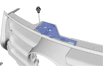
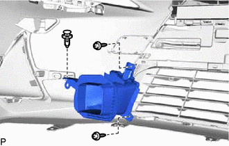
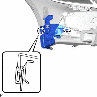
INSTALL FRONT BUMPER SIDE RETAINER LH
-
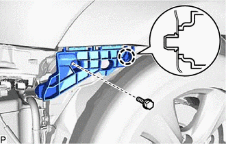
Engage the claw.
-
Install the front bumper side retainer LH with the bolt.
- Torque:
- 5.4 N*m { 55 kgf*cm, 48 in.*lbf }
-
-
INSTALL FRONT BUMPER SIDE RETAINER RH
Tech Tips
Use the same procedure as for the LH side.
-
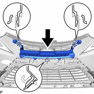
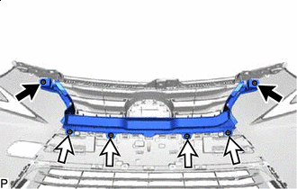
INSTALL FRONT BUMPER REINFORCEMENT
-
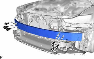
Install the front bumper reinforcement with the 6 bolts.
- Torque:
- 29 N*m { 296 kgf*cm, 21 ft.*lbf }
-
-
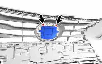
INSTALL POP-UP HOOD CHAMBER WITH SENSOR ASSEMBLY
-
INSTALL FRONT BUMPER ENERGY ABSORBER
-
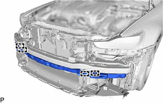
Engage the 4 guides to install the front bumper energy absorber.
-
-
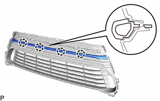
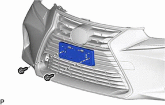
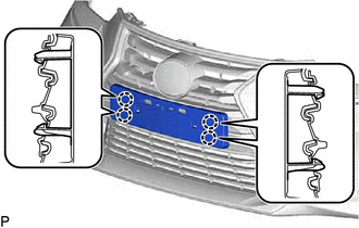
INSTALL NO. 3 RADIATOR GRILLE MOULDING
-
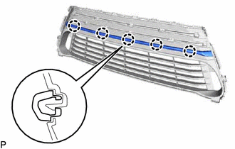
Engage the 5 claws.
-
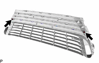
Install the No. 3 radiator grille moulding with the 2 screws.
-
-
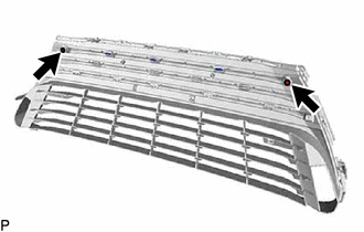
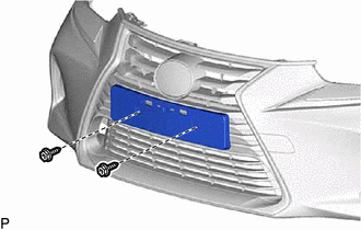
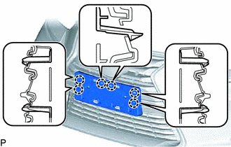
INSTALL NO. 2 RADIATOR GRILLE MOULDING
-
Engage the 4 claws.
-
Install the No. 2 radiator grille moulding with the 2 screws.
-
-
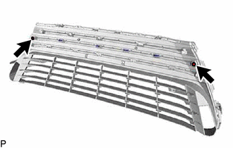
INSTALL NO. 1 RADIATOR GRILLE MOULDING
-

Engage the 3 claws.
-
Install the No. 1 radiator grille moulding with the 2 screws.
-
-
INSTALL INSIDE RADIATOR GRILLE
-
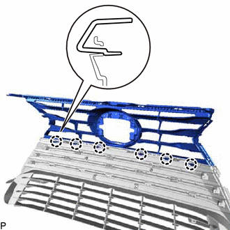
Engage the 6 claws to install the inside radiator grille.
-
-
INSTALL LOWER RADIATOR GRILLE MOULDING
-
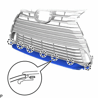
Engage the 7 claws to install the lower radiator grille moulding.
-
-
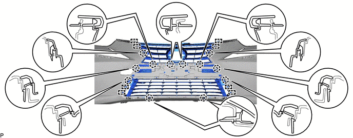
INSTALL RADIATOR GRILLE MOULDING
-
Engage the 14 claws to install the radiator grille moulding.
-
-
INSTALL RADIATOR GRILLE BRACKET
-
Engage the 3 guides.
-
Install the radiator grille bracket with the clip.
-
-
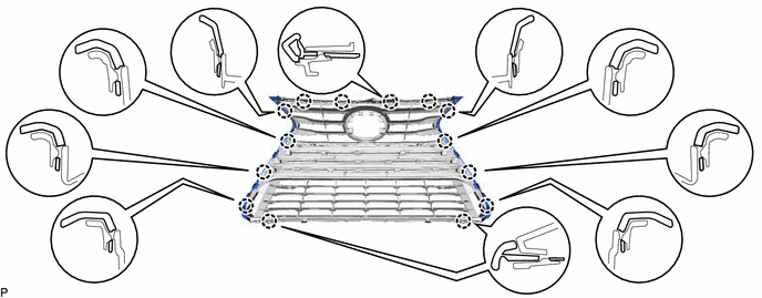
INSTALL RADIATOR GRILLE ASSEMBLY
-
Engage the 8 guides and 12 claws.
-
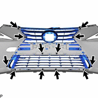
Install the radiator grille assembly with the 12 screws.
-
-
INSTALL RADIATOR GRILLE (OR FRONT PANEL) EMBLEM
-
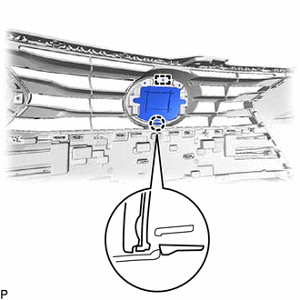
Engage the pin and claw.
-
Install the radiator grille (or front panel) emblem with the 2 screws.
-
-
INSTALL NO. 1 FRONT BUMPER BRACKET LH
-
Engage the 2 guides.
-
Install the No. 1 front bumper bracket LH with the clip.
-
-
INSTALL NO. 1 FRONT BUMPER BRACKET RH
Tech Tips
Use the same procedure as for the LH side.
-
INSTALL RADIATOR GRILLE PROTECTOR
-
Engage the 7 clips and install the radiator grille protector.
-
-
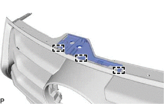
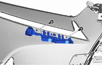
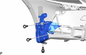
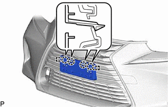
INSTALL FRONT ENERGY ABSORBER MOUNTING PLATE
-
Engage the 3 claws as shown in the illustration.
-

Clip 
Screw Install the 2 clips.
-
Install the front energy absorber mounting plate with the 4 screws.
-
-
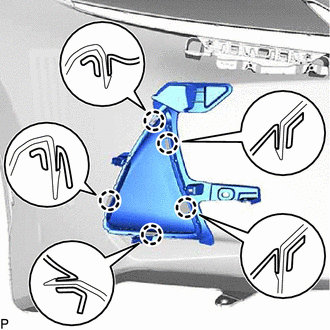
INSTALL LOWER FRONT BUMPER COVER
-
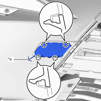
*a Hook Engage the hook.
-
Engage the 4 claws to install the lower front bumper cover.
-
-
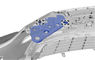
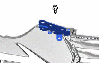
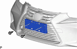
INSTALL NO. 2 FRONT BUMPER RETAINER BRACKET
-
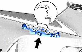
Engage the 2 claws as shown in the illustration.
-
Install the No. 2 front bumper retainer bracket with the 2 screws.
-
-
INSTALL NO. 1 FRONT BUMPER RETAINER BRACKET
Tech Tips
Use the same procedure as for the No. 2 front bumper retainer bracket.
-
INSTALL NO. 1 MOULDING TAPE
Tech Tips
Use the same procedure for the RH side and LH side.
-
Clean the installation surface of the No. 1 moulding tape.
-
Remove any remaining double-sided tape from the front bumper cover.
Note
-
If there is any foreign matter on the front bumper cover when the No. 1 moulding tape is installed, adhesion failure may occur.
-
Do not use a screwdriver or other tool to remove the double-sided tape as the front bumper cover may be damaged, possibly leading to adhesion failure.
-
-
Wipe off any tape adhesive residue with cleaner.
-
-
Install a new No. 1 moulding tape.
CAUTION:
-
Do not touch the heat light, as doing so may cause in burns.
-
Touching heated parts for a long time may result in burns.
Tech Tips
If the temperature of the No. 1 moulding tape or its installation surface on the front bumper cover is below 15°C (59°F), adhesion failure may occur. Use a heat light to heat the No. 1 moulding tape and its installation surface on the front bumper cover to the recommended temperature (15 to 40°C (59 to 104°F)).
-
Remove the release paper from a new No. 1 moulding tape.
Tech Tips
After removing the release paper, keep the exposed adhesive free from foreign matter.
-
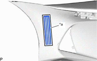
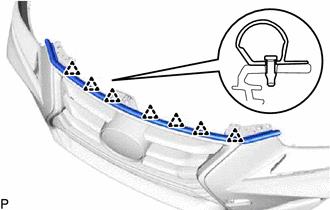
*a Line Install the No. 1 moulding tape to the front bumper cover as shown in the illustration.
Note
If the No. 1 moulding tape has been removed, it must be replaced with a new one as it may be deformed or the strength of its adhesive may be deteriorated.
Tech Tips
Make sure not to touch the exposed adhesive of the No. 1 moulding tape or the installation surface on the front bumper cover.
-
Using a squeegee, evenly press the No. 1 moulding tape to the front bumper cover with a force of 29 N (3 kgf, 6.5 lbf) or more.
Tech Tips
-
Make sure that the corners of the No. 1 moulding tape are not damaged or peeling off.
-
After installing the No. 1 moulding tape, leave the front bumper cover in an area with an ambient temperature of 15°C (59°F) or more for 30 minutes or more to allow the adhesive to set.
-
-
Remove the protector sheet from the No. 1 moulding tape.
-
-
-
INSTALL LOWER RADIATOR GRILLE LH
-
Engage the 5 claws to install the lower radiator grille LH.
-
-
INSTALL LOWER RADIATOR GRILLE RH
Tech Tips
Use the same procedure as for the LH side.
-
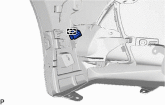
INSTALL FRONT FENDER LINER RETAINER
-
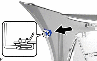
Engage the claw to install the front fender liner retainer as shown in the illustration.
Tech Tips
Use the same procedure as for the LH side.
-
-
INSTALL NO. 2 COOL AIR INTAKE DUCT
-
Install the clip.
-
Install the No. 2 cool air intake duct with the 2 screws.
-
-
INSTALL NO. 1 COOL AIR INTAKE DUCT
Tech Tips
Use the same procedure as for the No. 2 cool air intake duct.
-
INSTALL FRONT BUMPER SIDE BRACKET LH
-
Engage the guide and claw.
-
Install the clip.
-
Install the front bumper side bracket LH with the 2 screws.
-
-
INSTALL FRONT BUMPER SIDE BRACKET RH
Tech Tips
Use the same procedure as for the LH side.
-
INSTALL CLEARANCE LIGHT ASSEMBLY LH
-
INSTALL CLEARANCE LIGHT ASSEMBLY RH
Tech Tips
Use the same procedure as for the LH side.
-
INSTALL FRONT BUMPER EXTENSION MOUNTING BRACKET
-
for Type A:
-
Engage the 2 guides and 4 claws.
-
Install the front bumper extension mounting bracket with the 2 screws.
-
-
for Type B:
-
Engage the 4 claws.
-
Install the front bumper extension mounting bracket with the 2 screws.
-
-
for Type C:
-
Engage the 6 claws.
-
Install the front bumper extension mounting bracket with the 2 screws.
-
-
-
INSTALL CONNECTOR BRACKET (w/o Intuitive Parking Assist System)
-
Engage the clamp to install the connector bracket.
-
-
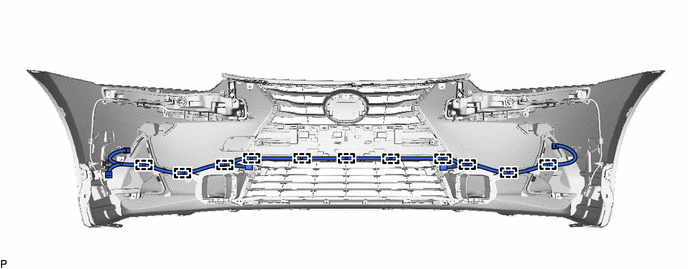
INSTALL NO. 4 ENGINE ROOM WIRE (w/ Intuitive Parking Assist System)
-
Engage the 11 clamps to install the No. 4 engine room wire.
-
-
INSTALL NO. 1 ULTRASONIC SENSOR RETAINER (w/ Intuitive Parking Assist System)
-
INSTALL NO. 1 ULTRASONIC SENSOR (w/ Intuitive Parking Assist System)
-
INSTALL NO. 2 ULTRASONIC SENSOR (w/ Intuitive Parking Assist System)
-
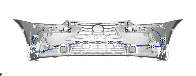
INSTALL HEADLIGHT CLEANER HOSE (w/ Headlight Cleaner System)
-
Engage the 14 clamps to install the headlight cleaner hose.
-
-
INSTALL HEADLIGHT WASHER COVER LH (w/ Headlight Cleaner System)
-
INSTALL HEADLIGHT WASHER COVER RH (w/ Headlight Cleaner System)
Tech Tips
Use the same procedure as for the LH side.
-
INSTALL HEADLIGHT WASHER ACTUATOR SUB-ASSEMBLY LH (w/ Headlight Cleaner System)
-
INSTALL HEADLIGHT WASHER ACTUATOR SUB-ASSEMBLY RH (w/ Headlight Cleaner System)
Tech Tips
Use the same procedure as for the LH side.
-
INSTALL MILLIMETER WAVE RADAR SENSOR ASSEMBLY (w/ Lexus Safety System+)