HEADLIGHT ASSEMBLY(for HID Headlight) DISASSEMBLY
PROCEDURE
-
REMOVE FRONT TURN SIGNAL LIGHT BULB
-
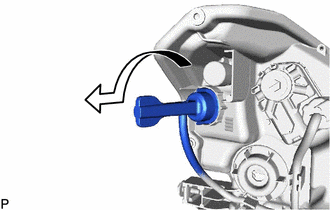
Turn the headlight cord with the front turn signal light bulb as shown in the illustration, and disconnect them as a unit.
-
Remove the front turn signal light bulb from the headlight cord.
-
-
REMOVE HEADLIGHT LIGHT CONTROL ECU SUB-ASSEMBLY
-
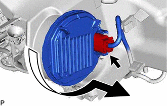
Disconnect the connector.
-
Turn the headlight light control ECU sub-assembly as shown in the illustration to separate it.
Note
-
Do not apply excessive force using a tool.
-
Do not damage the O-ring or allow it to become contaminated with foreign matter. If the O-ring is damaged or contaminated, water may get into the headlight assembly, resulting in a malfunction of the headlight light control ECU sub-assembly.
-
-
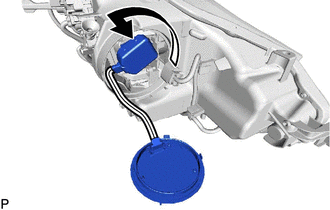
Turn the socket of the headlight light control ECU sub-assembly as shown in the illustration to remove it.
Note
Do not pull the headlight light control ECU sub-assembly with the socket connected.
-
-
REMOVE DISCHARGE HEADLIGHT BULB
-
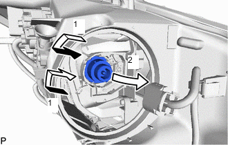
Release the set spring as indicated by the arrows, in the order shown in the illustration and remove the discharge headlight bulb.
Note
Do not touch the bulb glass.
-
-
REMOVE NO. 1 GEAR UNIT ASSEMBLY RH
-
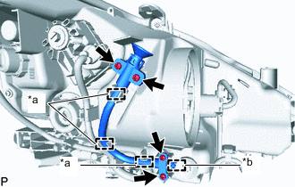
*a Clamp *b Guide Remove the 4 screws.
-
Disengage the 3 clamps and guide to remove the No. 1 gear unit assembly RH from the headlight unit.
-
-
REMOVE HEADLIGHT CORD
-
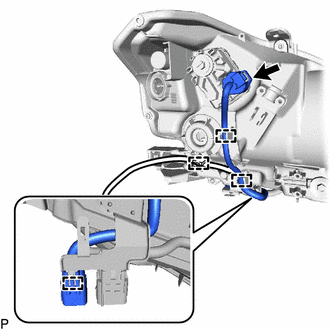
Disconnect the connector.
-
Disengage the 4 clamps to remove the headlight cord.
-
-
REMOVE HEADLIGHT LEVELING MOTOR
-
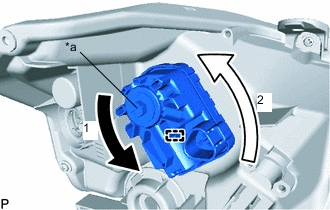
*a Aiming Screw Turn the aiming screw of the headlight leveling motor in the direction indicated by the arrow (1) shown in the illustration.
Tech Tips
-
Turn the aiming screw until the headlight leveling motor can be moved in the direction indicated by the arrow (2) shown in the illustration.
-
Make sure to remember the number of aiming screw rotations.
-
-
Turn the headlight leveling motor in the direction indicated by the arrow (2) shown in the illustration to disengage the pin.
Tech Tips
When removing the headlight leveling motor of the headlight assembly RH, turn the headlight leveling motor in the opposite direction of the arrow (2) shown in the illustration.
-
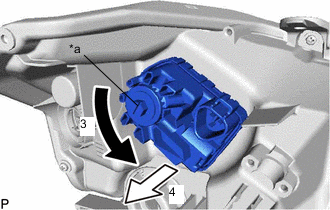
*a Aiming Screw Turn the aiming screw of the headlight leveling motor in the direction indicated by the arrow (3) shown in the illustration to disengage the shaft.
Tech Tips
Make sure to remember the number of aiming screw rotations.
-
Pull out the headlight leveling motor in the direction indicated by the arrow (4) shown in the illustration to remove it.
-
-
REMOVE HEADLIGHT LEVELING MOTOR BASE PACKING
-
Remove the headlight leveling motor base packing.
Note
After the headlight leveling motor base packing is removed, be sure to replace it with a new one. Failure to do so may cause water ingress.
-