LIGHTING SYSTEM Power Source Circuit
DESCRIPTION
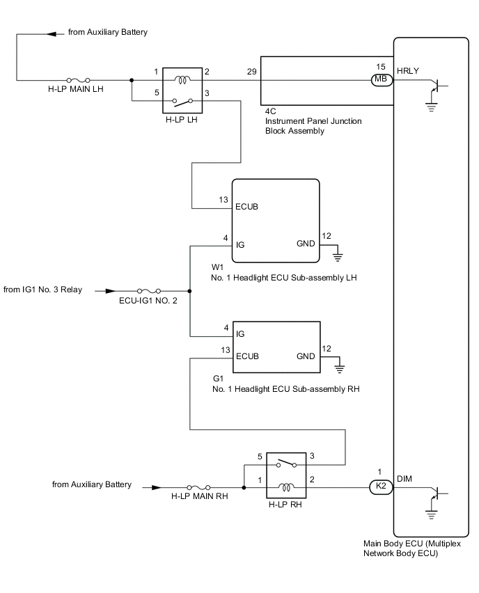
The main body ECU (multiplex network body ECU) receives IG signals and supplies power to the No. 1 headlight ECU sub-assemblies via the H-LP relays.
WIRING DIAGRAM
CAUTION / NOTICE / HINT
Note
-
Inspect the fuses for circuits related to this system before performing the following procedure.
-
Before replacing the main body ECU (multiplex network body ECU), refer to Service Bulletin.
PROCEDURE
-
INSPECT NO. 1 HEADLIGHT ECU SUB-ASSEMBLY (ECUB TERMINAL VOLTAGE)
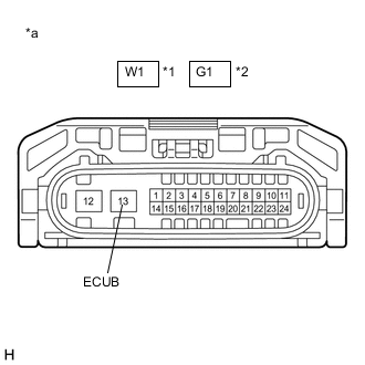
*1 No. 1 Headlight ECU Sub-assembly LH *2 No. 1 Headlight ECU Sub-assembly RH *a Component without harness connected
(No. 1 Headlight ECU Sub-assembly)
-
Disconnect the W1 No. 1 headlight ECU sub-assembly LH connector.
-
Disconnect the G1 No. 1 headlight ECU sub-assembly RH connector.
-
Measure the voltage according to the value(s) in the table below.
Standard Voltage No. 1 Headlight ECU Sub-assembly LH Tester Connection Condition Specified Condition W1-13 (ECUB) - Body ground Power switch on (IG) or light control switch in tail or head position 11 to 14 V No. 1 Headlight ECU Sub-assembly RH Tester Connection Condition Specified Condition G1-13 (ECUB) - Body ground Power switch on (IG) or light control switch in tail or head position 11 to 14 V Result Result Proceed to OK A NG (No. 1 Headlight ECU Sub-assembly LH) B NG (No. 1 Headlight ECU Sub-assembly RH) C
B 
INSPECT H-LP LH RELAY Click here
C
INSPECT H-LP RH RELAY Click here
A 
-
-
INSPECT NO. 1 HEADLIGHT ECU SUB-ASSEMBLY (IG TERMINAL VOLTAGE)
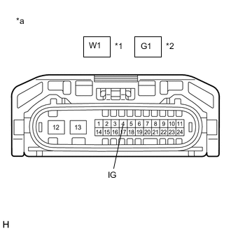
*1 No. 1 Headlight ECU Sub-assembly LH *2 No. 1 Headlight ECU Sub-assembly RH *a Component without harness connected
(No. 1 Headlight ECU Sub-assembly)
-
Measure the voltage according to the value(s) in the table below.
Standard Voltage No. 1 Headlight ECU Sub-assembly LH Tester Connection Condition Specified Condition W1-4 (IG) - Body ground Power switch on (IG) 11 to 14 V No. 1 Headlight ECU Sub-assembly RH Tester Connection Condition Specified Condition G1-4 (IG) - Body ground Power switch on (IG) 11 to 14 V Result Proceed to OK NG
NG 
REPAIR OR REPLACE HARNESS OR CONNECTOR
OK
-
-
CHECK HARNESS AND CONNECTOR (NO. 1 HEADLIGHT ECU SUB-ASSEMBLY - BODY GROUND)
-
Measure the resistance according to the value(s) in the table below.
Standard Resistance No. 1 Headlight ECU Sub-assembly LH Tester Connection Condition Specified Condition W1-12 (GND) - Body ground Always Below 1 Ω No. 1 Headlight ECU Sub-assembly RH Tester Connection Condition Specified Condition G1-12 (GND) - Body ground Always Below 1 Ω Result Proceed to OK NG
OK
PROCEED TO NEXT SUSPECTED AREA SHOWN IN PROBLEM SYMPTOMS TABLE Click here
NG
REPAIR OR REPLACE HARNESS OR CONNECTOR
-
-
INSPECT H-LP LH RELAY
-
Inspect the H-LP LH relay.
Result Proceed to OK NG
NG
REPLACE H-LP LH RELAY
OK
-
-
CHECK HARNESS AND CONNECTOR (H-LP LH RELAY - NO. 1 HEADLIGHT ECU SUB-ASSEMBLY LH)
-
Measure the resistance according to the value(s) in the table below.
Standard Resistance Tester Connection Condition Specified Condition 3 (H-LP LH Relay) - W1-13 (ECUB) Always Below 1 Ω 3 (H-LP LH Relay) or W1-13 (ECUB) - Body ground Always 10 kΩ or higher Result Proceed to OK NG
NG
REPAIR OR REPLACE HARNESS OR CONNECTOR
OK
-
-
CHECK HARNESS AND CONNECTOR (POWER SOURCE - H-LP LH RELAY)
-
Measure the voltage according to the value(s) in the table below.
Standard Voltage Tester Connection Condition Specified Condition 1 (H-LP LH Relay) - Body ground Power switch off 11 to 14 V 5 (H-LP LH Relay) - Body ground Power switch off 11 to 14 V Result Proceed to OK NG
NG
REPAIR OR REPLACE HARNESS OR CONNECTOR
OK
-
-
CHECK HARNESS AND CONNECTOR (H-LP LH RELAY - MAIN BODY ECU (MULTIPLEX NETWORK BODY ECU))
-
Disconnect the 4C instrument panel junction block assembly connector.
-
Measure the resistance according to the value(s) in the table below.
Standard Resistance Tester Connection Condition Specified Condition 2 (H-LP LH Relay) - 4C-29 Always Below 1 Ω 2 (H-LP LH Relay) or 4C-29 - Body ground Always 10 kΩ or higher Result Proceed to OK NG
NG
REPAIR OR REPLACE HARNESS OR CONNECTOR
OK
-
-
INSPECT INSTRUMENT PANEL JUNCTION BLOCK ASSEMBLY
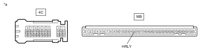
*a Component without harness connected
(Instrument Panel Junction Block Assembly)
- -
-
Remove the instrument panel junction block assembly.
-
Remove the main body ECU (multiplex network body ECU) from the instrument panel junction block assembly.
-
Measure the resistance according to the value(s) in the table below.
Standard Resistance Tester Connection Condition Specified Condition 4C-29 - MB-15 (HRLY) Always Below 1 Ω Result Proceed to OK NG
OK
REPLACE MAIN BODY ECU (MULTIPLEX NETWORK BODY ECU) Click here
NG
REPLACE INSTRUMENT PANEL JUNCTION BLOCK ASSEMBLY Click here
-
-
INSPECT H-LP RH RELAY
-
Inspect the H-LP RH relay.
Result Proceed to OK NG
NG
REPLACE H-LP RH RELAY
OK
-
-
CHECK HARNESS AND CONNECTOR (H-LP RH RELAY - NO. 1 HEADLIGHT ECU SUB-ASSEMBLY RH)
-
Measure the resistance according to the value(s) in the table below.
Standard Resistance Tester Connection Condition Specified Condition 3 (H-LP RH Relay) - G1-13 (ECUB) Always Below 1 Ω 3 (H-LP RH Relay) or G1-13 (ECUB) - Body ground Always 10 kΩ or higher Result Proceed to OK NG
NG
REPAIR OR REPLACE HARNESS OR CONNECTOR
OK
-
-
CHECK HARNESS AND CONNECTOR (POWER SOURCE - H-LP RH RELAY)
-
Measure the voltage according to the value(s) in the table below.
Standard Voltage Tester Connection Condition Specified Condition 1 (H-LP RH Relay) - Body ground Power switch off 11 to 14 V 5 (H-LP RH Relay) - Body ground Power switch off 11 to 14 V Result Proceed to OK NG
NG
REPAIR OR REPLACE HARNESS OR CONNECTOR
OK
-
-
CHECK HARNESS AND CONNECTOR (H-LP RH RELAY - MAIN BODY ECU (MULTIPLEX NETWORK BODY ECU))
-
Disconnect the K2 main body ECU (multiplex network body ECU) connector.
-
Measure the resistance according to the value(s) in the table below.
Standard Resistance Tester Connection Condition Specified Condition 2 (H-LP RH Relay) - K2-1 (DIM) Always Below 1 Ω 2 (H-LP RH Relay) or K2-1 (DIM) - Body ground Always 10 kΩ or higher Result Proceed to OK NG
OK
REPLACE MAIN BODY ECU (MULTIPLEX NETWORK BODY ECU) Click here
NG
REPAIR OR REPLACE HARNESS OR CONNECTOR
-