LIGHTING SYSTEM Door Mirror Foot Light Circuit
DESCRIPTION
-
for Power mirror control system (w/o Memory)
The main body ECU (multiplex network body ECU) controls the door mirror foot lights.
-
for Power mirror control system (w/ Memory)
The outer mirror control ECU assembly receives the signal from the main body ECU (multiplex network body ECU) to control the door mirror foot light.
WIRING DIAGRAM
-
for POWER MIRROR CONTROL SYSTEM (w/o Memory)
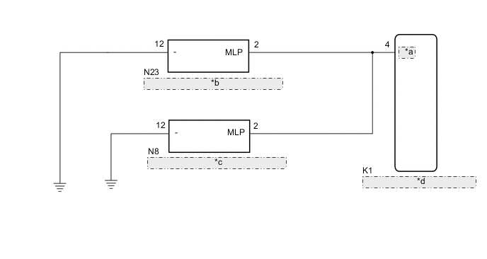
*a MILE *b Outer Rear View Mirror Assembly LH *c Outer Rear View Mirror Assembly RH *d Main Body ECU (Multiplex Network Body ECU) -
for POWER MIRROR CONTROL SYSTEM (w/ Memory)
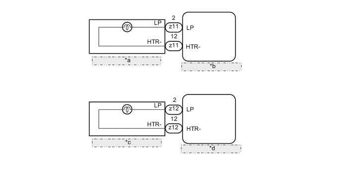
*a Outer Rear View Mirror Assembly LH *b Outer Mirror Control ECU Assembly LH *c Outer Rear View Mirror Assembly RH *d Outer Mirror Control ECU Assembly RH
CAUTION / NOTICE / HINT
Note
Before replacing the main body ECU (multiplex network body ECU), refer to Service Bulletin.
PROCEDURE
-
CHECK VEHICLE TYPE
-
Check the vehicle type.
Result Result Proceed to Power mirror control system (w/o Memory) A Power mirror control system (w/ Memory) B
B 
PERFORM ACTIVE TEST USING GTS Click here
A 
-
-
PERFORM ACTIVE TEST USING GTS
-
Connect the GTS to the DLC3.
-
Turn the power switch on (IG).
-
Turn the GTS on.
-
Enter the following menus: Body Electrical / Main Body / Active Test.
-
Check that the high beam headlights illuminate.
Body Electrical > Main Body > Active TestTester Display Measurement Item Control Range Diagnostic Note Side Mirror Foot Light Door mirror foot lights ON/OFF *1
-
*1: for Power Mirror Control System (w/o Memory)
Body Electrical > Main Body > Active TestTester Display Side Mirror Foot Light OK Door mirror foot lights illuminate. Result Result Proceed to OK A NG (One side door mirror foot light does not illuminate) B NG (Both side door mirror foot lights do not illuminate) C -
A 
PROCEED TO NEXT SUSPECTED AREA SHOWN IN PROBLEM SYMPTOMS TABLE Click here
C
REPAIR OR REPLACE HARNESS OR CONNECTOR
B
-
-
INSPECT OUTER REAR VIEW MIRROR ASSEMBLY
-
Remove the outer rear view mirror assembly that does not illuminate.
-
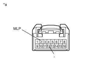
*a Component without harness connected
(Outer Rear View Mirror Assembly LH)
(Outer Rear View Mirror Assembly RH)
Connect a positive (+) lead from the auxiliary battery to terminal 2 (MLP) and a negative (-) lead to terminal 12 (-).
-
Check that the door mirror foot light illuminates.
OK Door mirror foot light illuminates. Result Result Proceed to OK A NG (Outer rear view mirror assembly LH does not illuminate.) B NG (Outer rear view mirror assembly RH does not illuminate.) C
B
REPLACE OUTER REAR VIEW MIRROR ASSEMBLY LH Click here
C
REPLACE OUTER REAR VIEW MIRROR ASSEMBLY RH Click here
A
-
-
CHECK HARNESS AND CONNECTOR (MAIN BODY ECU (MULTIPLEX NETWORK BODY ECU) - OUTER REAR VIEW MIRROR ASSEMBLY)
-
Disconnect the K1 main body ECU (multiplex network body ECU) connector.
-
Disconnect the N23*1 or N8*2 outer rear view mirror assembly connector.
-
*1: for LH Side
-
*2: for RH Side
-
-
Measure the resistance according to the value(s) in the table below.
Standard Resistance for LH Side Tester Connection Condition Specified Condition N23-2 (MLP) - K1-4 (MILE) Always Below 1 Ω K1-4 (MILE) - Body ground Always 10 kΩ or higher for RH Side Tester Connection Condition Specified Condition N8-2 (MLP) - K1-4 (MILE) Always Below 1 Ω K1-4 (MILE) - Body ground Always 10 kΩ or higher Result Proceed to OK NG
OK
REPLACE MAIN BODY ECU (MULTIPLEX NETWORK BODY ECU) Click here
NG
REPAIR OR REPLACE HARNESS OR CONNECTOR
-
-
PERFORM ACTIVE TEST USING GTS
-
Connect the GTS to the DLC3.
-
Turn the power switch on (IG).
-
Turn the GTS on.
-
Enter the following menus: Body Electrical / Mirror L or Mirror R / Active Test.
-
Check that the door mirror foot lights illuminate.
Body Electrical > Mirror L > Active TestTester Display Measurement Item Control Range Diagnostic Note Foot Light Door mirror foot light LH ON/OFF *1
Body Electrical > Mirror R > Active TestTester Display Measurement Item Control Range Diagnostic Note Foot Light Door mirror foot light RH ON/OFF *1
-
*1: for Power mirror control system (w/ Memory)
Body Electrical > Mirror L > Active TestTester Display Foot Light
Body Electrical > Mirror R > Active TestTester Display Foot Light OK Door mirror foot lights illuminate. Result Result Proceed to OK A NG (Door mirror foot light LH does not illuminate) B NG (Door mirror foot light RH does not illuminate) C -
A
PROCEED TO NEXT SUSPECTED AREA SHOWN IN PROBLEM SYMPTOMS TABLE Click here
C
INSPECT OUTER REAR VIEW MIRROR ASSEMBLY RH Click here
B
-
-
INSPECT OUTER REAR VIEW MIRROR ASSEMBLY LH
-
Remove the outer rear view mirror assembly LH.
-
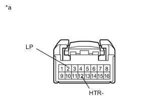
*a Component without harness connected
(Outer Rear View Mirror Assembly LH)
Connect a positive (+) lead from the auxiliary battery to terminal 2 (LP) and a negative (-) lead to terminal 12 (HTR-).
-
Check that the door mirror foot light LH illuminates.
OK Door mirror foot light illuminates. Result Proceed to OK NG
OK
REPLACE OUTER MIRROR CONTROL ECU ASSEMBLY LH Click here
NG
REPLACE OUTER REAR VIEW MIRROR ASSEMBLY LH Click here
-
-
INSPECT OUTER REAR VIEW MIRROR ASSEMBLY RH
-
Remove the outer rear view mirror assembly RH.
-
*a Component without harness connected
(Outer Rear View Mirror Assembly RH)
Connect a positive (+) lead from the auxiliary battery to terminal 2 (LP) and a negative (-) lead to terminal 12 (HTR-).
-
Check that the door mirror foot light RH illuminates.
OK Door mirror foot light illuminates. Result Proceed to OK NG
OK
REPLACE OUTER MIRROR CONTROL ECU ASSEMBLY RH Click here
NG
REPLACE OUTER REAR VIEW MIRROR ASSEMBLY RH Click here
-