LIGHTING SYSTEM Back-up Light Circuit
DESCRIPTION
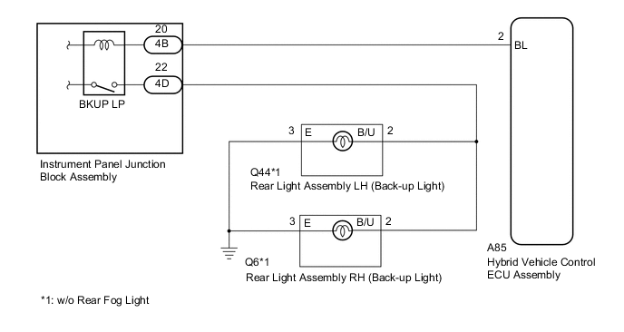
The hybrid vehicle control ECU assembly controls the back-up lights via the BKUP LP relay.
WIRING DIAGRAM
CAUTION / NOTICE / HINT
Note
Inspect the fuses and bulbs for circuits related to this system before performing the following inspection procedure.
PROCEDURE
-
CHECK FOR DTC (HYBRID CONTROL SYSTEM)
-
Clear the DTCs.
Powertrain > Hybrid Control > Clear DTCs -
Check for DTCs.
Powertrain > Hybrid Control > Trouble CodesResult Result Proceed to Hybrid control system DTCs are not output. A Hybrid control system DTCs are output. B
B 
GO TO HYBRID CONTROL SYSTEM (DIAGNOSTIC TROUBLE CODE CHART) Click here
A 
-
-
CHECK HARNESS AND CONNECTOR (INSTRUMENT PANEL JUNCTION BLOCK ASSEMBLY - HYBRID VEHICLE CONTROL ECU ASSEMBLY)
-
Disconnect the 4B instrument panel junction block assembly connector.
-
Disconnect the A85 hybrid vehicle control ECU assembly connector.
-
Measure the resistance according to the value(s) in the table below.
Standard Resistance Tester Connection Condition Specified Condition 4B-20 - A85-2 (BL) Always Below 1 Ω 4B-20 - Body ground Always 10 kΩ or higher Result Proceed to OK NG
NG
REPAIR OR REPLACE HARNESS OR CONNECTOR
OK
-
-
CHECK HYBRID VEHICLE CONTROL ECU ASSEMBLY (OUTPUT VOLTAGE)
-
Reconnect the A85 hybrid vehicle control ECU assembly connector.
-
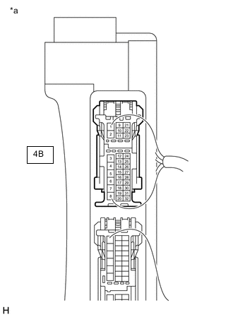
*a Component with wire harness connected
(Instrument Panel Junction Block Assembly)
Reconnect the 4B instrument panel junction block assembly connector.
-
Measure the voltage according to the value(s) in the table below.
Standard Voltage Tester Connection Condition Specified Condition 4B-20 - Body ground Power switch on (IG), shift lever not in R Below 1 V 4B-20 - Body ground Power switch on (IG), shift lever in R 11 to 14 V Result Proceed to OK NG
NG
REPLACE HYBRID VEHICLE CONTROL ECU ASSEMBLY Click here
OK
-
-
INSPECT INSTRUMENT PANEL JUNCTION BLOCK ASSEMBLY (OUTPUT VOLTAGE)
-
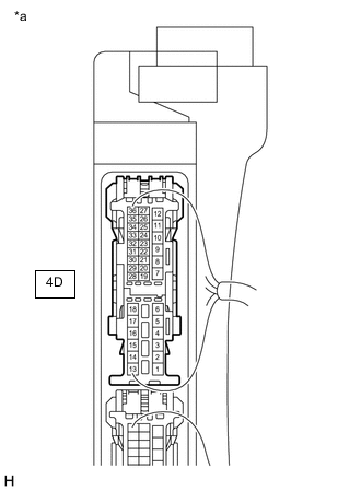
*a Component with wire harness connected
(Instrument Panel Junction Block Assembly)
Measure the voltage according to the value(s) in the table below.
Standard Voltage Tester Connection Condition Specified Condition 4D-22 - Body ground Power switch on (IG), shift lever not in R Below 1 V 4D-22 - Body ground Power switch on (IG), shift lever in R 11 to 14 V Result Proceed to OK NG
OK
REPAIR OR REPLACE HARNESS OR CONNECTOR (REAR LIGHT ASSEMBLY - INSTRUMENT PANEL JUNCTION BLOCK ASSEMBLY)
NG
REPLACE INSTRUMENT PANEL JUNCTION BLOCK ASSEMBLY Click here
-