LIGHTING SYSTEM Clearance Light/Daytime Running Light Circuit
DESCRIPTION
-
When the main body ECU (multiplex network body ECU) receives the light control switch position signal, it sends an illumination request signal to the No. 1 headlight ECU sub-assembly LH and illuminates the clearance lights.
Clearance light function:
-
When the operation conditions of the daytime running lights are met, the main body ECU (multiplex network body ECU) sends an illumination request signal to the No. 1 headlight ECU sub-assembly LH and illuminates the daytime running lights.
Daytime running light function:
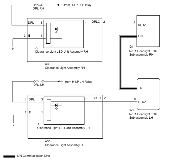
WIRING DIAGRAM
CAUTION / NOTICE / HINT
Note
-
Inspect the fuses for circuits related to this system before performing the following procedure.
-
If the No. 1 headlight ECU sub-assembly LH has been replaced, it is necessary to synchronize the vehicle information and initialize the No. 1 headlight ECU sub-assembly LH.
PROCEDURE
-
PERFORM ACTIVE TEST USING GTS
-
Connect the GTS to the DLC3.
-
Turn the power switch on (IG).
-
Turn the GTS on.
-
Enter the following menus: Body Electrical / HL AutoLeveling / Active Test.
-
Perform the Active Test according to the display on the GTS.
Body Electrical > HL AutoLeveling > Active TestTester Display Measurement Item Control Range Diagnostic Note Clearance Light Clearance lights OFF or ON - Daytime Running Light Daytime running lights OFF or ON -
Body Electrical > HL AutoLeveling > Active TestTester Display Clearance Light
Body Electrical > HL AutoLeveling > Active TestTester Display Daytime Running Light OK Clearance lights and daytime running lights illuminate. Result Result Proceed to OK A NG (for LH Side) B NG (for RH Side) C
A 
PROCEED TO NEXT SUSPECTED AREA SHOWN IN PROBLEM SYMPTOMS TABLE Click here
C 
CHECK HARNESS AND CONNECTOR (CLEARANCE LIGHT ASSEMBLY RH - AUXILIARY BATTERY) Click here
B 
-
-
CHECK HARNESS AND CONNECTOR (CLEARANCE LIGHT ASSEMBLY LH - AUXILIARY BATTERY)
-
Disconnect the A35 clearance light assembly LH connector.
-
Measure the voltage according to the value(s) in the table below.
Standard Voltage Tester Connection Condition Specified Condition A35-1 (DRL) - Body ground Light control switch in tail or head position 11 to 14 V Result Proceed to OK NG
NG
REPAIR OR REPLACE HARNESS OR CONNECTOR
OK
-
-
CHECK HARNESS AND CONNECTOR (CLEARANCE LIGHT ASSEMBLY LH - BODY GROUND)
-
Measure the resistance according to the value(s) in the table below.
Standard Resistance Tester Connection Condition Specified Condition A35-3 (E) - Body ground Always Below 1 Ω Result Proceed to OK NG
NG
REPAIR OR REPLACE HARNESS OR CONNECTOR
OK
-
-
CHECK HARNESS AND CONNECTOR (CLEARANCE LIGHT ASSEMBLY LH - NO. 1 HEADLIGHT ECU SUB-ASSEMBLY LH)
-
Disconnect the W1 No. 1 headlight ECU sub-assembly LH connector.
-
Measure the resistance according to the value(s) in the table below.
Standard Resistance Tester Connection Condition Specified Condition A35-2 (DRLC) - W1-8 (RLD2) Always Below 1 Ω A35-2 (DRLC) or W1-8 (RLD2) - Body ground Always 10 kΩ or higher Result Proceed to OK NG
NG
REPAIR OR REPLACE HARNESS OR CONNECTOR
OK
-
-
INSPECT CLEARANCE LIGHT LED UNIT ASSEMBLY LH
-
Remove the clearance light assembly LH.
-
Remove the clearance light LED unit assembly LH.
-
Inspect the clearance light LED unit assembly LH.
Result Proceed to OK NG
OK
REPLACE CLEARANCE LIGHT ASSEMBLY LH Click here
NG
REPLACE CLEARANCE LIGHT LED UNIT ASSEMBLY LH Click here
-
-
CHECK HARNESS AND CONNECTOR (CLEARANCE LIGHT ASSEMBLY RH - AUXILIARY BATTERY)
-
Disconnect the A3 clearance light assembly RH connector.
-
Measure the voltage according to the value(s) in the table below.
Standard Voltage Tester Connection Condition Specified Condition A3-1 (DRL) - Body ground Light control switch in tail or head position 11 to 14 V Result Proceed to OK NG
NG
REPAIR OR REPLACE HARNESS OR CONNECTOR
OK
-
-
CHECK HARNESS AND CONNECTOR (CLEARANCE LIGHT ASSEMBLY RH - BODY GROUND)
-
Measure the resistance according to the value(s) in the table below.
Standard Resistance Tester Connection Condition Specified Condition A3-3 (E) - Body ground Always Below 1 Ω Result Proceed to OK NG
NG
REPAIR OR REPLACE HARNESS OR CONNECTOR
OK
-
-
CHECK HARNESS AND CONNECTOR (CLEARANCE LIGHT ASSEMBLY RH - NO. 1 HEADLIGHT ECU SUB-ASSEMBLY RH)
-
Disconnect the G1 No. 1 headlight ECU sub-assembly RH connector.
-
Measure the resistance according to the value(s) in the table below.
Standard Resistance Tester Connection Condition Specified Condition A3-2 (DRLC) - G1-8 (RLD2) Always Below 1 Ω A3-2 (DRLC) or G1-8 (RLD2) - Body ground Always 10 kΩ or higher Result Proceed to OK NG
NG
REPAIR OR REPLACE HARNESS OR CONNECTOR
OK
-
-
INSPECT CLEARANCE LIGHT LED UNIT ASSEMBLY RH
-
Remove the clearance light assembly RH.
-
Remove the clearance light LED unit assembly RH.
-
Inspect the clearance light LED unit assembly RH.
Result Proceed to OK NG
OK
REPLACE CLEARANCE LIGHT ASSEMBLY RH Click here
NG
REPLACE CLEARANCE LIGHT LED UNIT ASSEMBLY RH Click here
-