LIGHTING SYSTEM, Diagnostic DTC:B242E
| DTC Code | DTC Name |
|---|---|
| B242E | Open in IG Circuit |
DESCRIPTION
This DTC is stored when a malfunction occurs in the No. 1 headlight ECU sub-assembly LH IG power source circuit. The No. 1 headlight ECU sub-assembly LH stores DTC B242E.
| DTC No. | Detection Item | DTC Detection Condition | Trouble Area |
|---|---|---|---|
| B242E | Open in IG Circuit | Open in the No. 1 headlight ECU sub-assembly LH IG power source circuit |
|
WIRING DIAGRAM
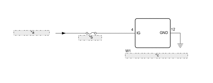
| *a | from IG1 NO. 3 Relay |
| *b | ECU-IG1 NO. 2 |
| *c | No. 1 Headlight ECU Sub-assembly LH |
CAUTION / NOTICE / HINT
Note
-
Inspect the fuses for circuits related to this system before performing the following procedure.
-
If the No. 1 headlight ECU sub-assembly LH has been replaced, it is necessary to synchronize the vehicle information and initialize the No. 1 headlight ECU sub-assembly LH.
PROCEDURE
-
CLEAR DTC
-
Connect the GTS to the DLC3.
-
Turn the power switch on (IG).
-
Turn the GTS on.
-
Enter the following menus: Body Electrical / HL AutoLeveling / Trouble Codes.
-
Clear the DTCs.
Body Electrical > HL AutoLeveling > Clear DTCsResult Proceed to NEXT
NEXT 
-
-
CHECK FOR DTC
-
Connect the GTS to the DLC3.
-
Turn the power switch on (IG).
-
Turn the GTS on.
-
Enter the following menus: Body Electrical / HL AutoLeveling / Trouble Codes.
-
Check for DTCs.
Body Electrical > HL AutoLeveling > Trouble CodesOK DTC B242E is not output. Result Proceed to OK NG
OK 
USE SIMULATION METHOD TO CHECK Click here
NG
-
-
INSPECT NO. 1 HEADLIGHT ECU SUB-ASSEMBLY LH (IG TERMINAL VOLTAGE)
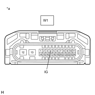
*a Component without harness connected
(No. 1 Headlight ECU Sub-assembly LH)
-
Disconnect the W1 No. 1 headlight ECU sub-assembly LH connector.
-
Measure the voltage according to the value(s) in the table below.
Standard Voltage Tester Connection Condition Specified Condition W1-4 (IG) - Body ground Power switch off Below 1 V W1-4 (IG) - Body ground Power switch on (IG) 11 to 14 V Result Proceed to OK NG
NG
REPAIR OR REPLACE HARNESS OR CONNECTOR
OK
-
-
CHECK HARNESS AND CONNECTOR (NO. 1 HEADLIGHT ECU SUB-ASSEMBLY LH - BODY GROUND)
-
Measure the resistance according to the value(s) in the table below.
Standard Resistance Tester Connection Condition Specified Condition W1-12 (GND) - Body ground Always Below 1 Ω Result Proceed to OK NG
OK
REPLACE NO. 1 HEADLIGHT ECU SUB-ASSEMBLY LH Click here
NG
REPAIR OR REPLACE HARNESS OR CONNECTOR
-