LIGHTING SYSTEM, Diagnostic DTC:B1244
| DTC Code | DTC Name |
|---|---|
| B1244 | Light Sensor Circuit Malfunction |
DESCRIPTION
The automatic light control sensor detects ambient light. The sensor creates an electrical signal based on the amount of light detected, and sends the signal to the main body ECU (multiplex network body ECU). The main body ECU (multiplex network body ECU) turns on or off the headlights and taillights according to the signal.
| DTC No. | Detection Item | DTC Detection Condition | Trouble Area |
|---|---|---|---|
| B1244 | Light Sensor Circuit Malfunction | Either of the following conditions is met:
|
|
WIRING DIAGRAM
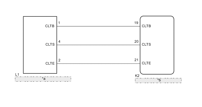
| *a | Automatic Light Control Sensor |
| *b | Main Body ECU (Multiplex Network Body ECU) |
CAUTION / NOTICE / HINT
Note
Before replacing the main body ECU (multiplex network body ECU), refer to Service Bulletin.
PROCEDURE
-
READ VALUE USING GTS
-
Connect the GTS to the DLC3.
-
Turn the power switch on (IG).
-
Turn the GTS on.
-
Enter the following menus: Body Electrical / Main Body / Data List.
-
Read the display on the GTS.
Body Electrical > Main Body > Data ListTester Display Measurement Item Range Normal Condition Diagnostic Note Light Sensor Illuminance Light control sensor illuminance 0 to 8191 lx Value is output according to ambient light level -
Body Electrical > Main Body > Data ListTester Display Light Sensor Illuminance OK Normal condition listed above is displayed. Result Proceed to OK NG
OK 
REPLACE MAIN BODY ECU (MULTIPLEX NETWORK BODY ECU) Click here
NG 
-
-
CHECK HARNESS AND CONNECTOR (MAIN BODY ECU (MULTIPLEX NETWORK BODY ECU) - AUTOMATIC LIGHT CONTROL SENSOR)
-
Disconnect the L1 automatic light control sensor connector.
-
Disconnect the K2 main body ECU (multiplex network body ECU) connector.
-
Measure the resistance according to the value(s) in the table below.
Standard Resistance Tester Connection Condition Specified Condition K2-21 (CLTE) - L1-2 (CLTE) Always Below 1 Ω K2-20 (CLTS) - L1-4 (CLTS) Always Below 1 Ω K2-19 (CLTB) - L1-1 (CLTB) Always Below 1 Ω K2-21 (CLTE) - Body ground Always 10 kΩ or higher K2-20 (CLTS) - Body ground Always 10 kΩ or higher K2-19 (CLTB) - Body ground Always 10 kΩ or higher Result Proceed to OK NG
NG
REPAIR OR REPLACE HARNESS OR CONNECTOR
OK
-
-
INSPECT MAIN BODY ECU (MULTIPLEX NETWORK BODY ECU)
-
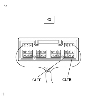
*a Component with harness connected
(Main Body ECU (Multiplex Network Body ECU))
Reconnect the K2 main body ECU (multiplex network body ECU) connector.
-
Measure the voltage according to the value(s) in the table below.
Standard Voltage Tester Connection Condition Specified Condition K2-19 (CLTB) - K2-21 (CLTE) Power switch off Below 1 V Power switch on (IG) 11 to 14 V Result Proceed to OK NG
NG
REPLACE MAIN BODY ECU (MULTIPLEX NETWORK BODY ECU) Click here
OK
-
-
INSPECT AUTOMATIC LIGHT CONTROL SENSOR
-
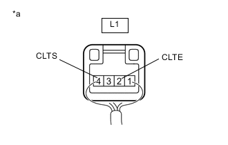
*a Component with harness connected
(Automatic Light Control Sensor)
Reconnect the L1 automatic light control sensor connector.
-
Connect an oscilloscope to the automatic light control sensor connector.
-
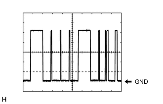
Check the waveform.
OK Tester Connection Tool Setting Condition Specified Condition L1-2 (CLTE) - L1-4 (CLTS) 2 V/DIV., 10 ms./DIV. Power switch on (IG), light control switch in AUTO position Correct waveform is as shown Tech Tips
The communication waveform changes according to the surrounding brightness.
Result Proceed to OK NG
OK
REPLACE MAIN BODY ECU (MULTIPLEX NETWORK BODY ECU) Click here
NG
REPLACE AUTOMATIC LIGHT CONTROL SENSOR Click here
-