LIGHTING SYSTEM TERMINALS OF ECU
-
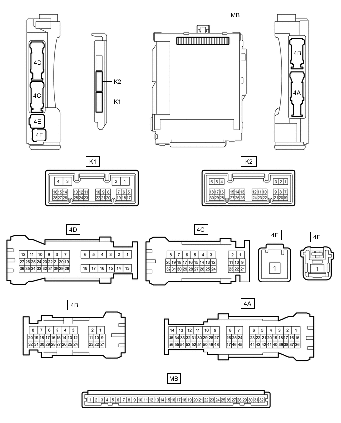
CHECK INSTRUMENT PANEL JUNCTION BLOCK ASSEMBLY AND MAIN BODY ECU (MULTIPLEX NETWORK BODY ECU)
-
Disconnect the instrument panel junction block assembly and main body ECU (multiplex network body ECU) connectors.
-
Measure the voltage and resistance according to the value(s) in the table below.
Terminal No.(Symbol) Wiring Color Terminal Description Condition Specified Condition 4F-1 - Body ground B - Body ground Auxiliary battery power supply Power switch off 11 to 14 V 4E-1 - Body ground B - Body ground Auxiliary battery power supply Power switch off 11 to 14 V 4B-7 - Body ground W-B - Body ground Ground Always Below 1 Ω -
Connect the instrument panel junction block assembly and main body ECU (multiplex network body ECU) connectors.
-
Measure the voltage and check for pulses according to the value(s) in the table below.
Terminal No. (Symbol) Wiring Color Terminal Description Condition Specified Condition 4C-15 - Body ground GR - Body ground Parking brake switch input Parking brake switch on Below 1 V Parking brake switch off 11 to 14 V 4C-29 - Body ground R - Body ground H-LP LH relay drive output Power switch on (IG) or light control switch in tail or head position Below 1 V Power switch off and light control switch off 11 to 14 V 4D-12 - Body ground*1 BE - Body ground Rear fog light drive output Light control switch in tail or head position, fog light switch in rear position Below 1 V Light control switch in tail or head position, fog light switch off 11 to 14 V 4D-28 - Body ground V - Body ground Taillight drive output Light control switch in tail or head position 11 to 14 V Light control switch off Below 1 V K1-4 (MILE) - Body ground*2 LG - Body ground Door mirror foot lights drive output Door mirror foot light operating 11 to 14 V Door mirror foot light not operating Below 3 V K2-1 (DIM) - Body ground V - Body ground H-LP RH relay drive output Power switch on (IG) or light control switch in tail or head position Below 1 V Power switch off and light control switch off 11 to 14 V K2-8 (A) - Body ground P - Body ground Light control switch AUTO position signal input Light control switch in AUTO position Below 1 V Light control switch not in AUTO position Pulse generation K2-10 (HF) - Body ground L - Body ground Dimmer switch high flash position signal input Dimmer switch in high flash position Below 1 V Dimmer switch not in high flash position Pulse generation K2-12 (HEAD) - Body ground Y - Body ground Light control switch head position input Light control switch in head position Below 1 V Light control switch not in head position Pulse generation K2-19 (CLTB) - K2-21 (CLTE) GR - W Automatic light control sensor power supply output Power switch off Below 1 V Power switch on (IG) 11 to 14 V K2-20 (CLTS) - Body ground R - Body ground Automatic light control sensor signal input Power switch off Below 1 V Power switch on (IG), light control switch in AUTO position Pulse generation
(See waveform 1)
K2-22 (TAIL) - Body ground B - Body ground Light control switch tail position signal input Light control switch in tail or head position Below 1 V Light control switch not in tail or head position Pulse generation K2-23 (RFOG) - Body ground*1 P - Body ground Fog light switch rear position input Fog light switch in rear position Below 1 V Fog light switch off Pulse generation K2-24 (HU) - Body ground V - Body ground Dimmer switch high position signal input Dimmer switch in high position Below 1 V Dimmer switch not in high position Pulse generation
-
*1: w/ Rear Fog Light
-
*2: for Power Mirror Control System (w/o Memory)
-
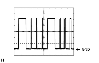
Waveform 1
Item Content Tester Connection K2-20 (CLTS) - Body ground Tool setting 2 V/DIV., 10 ms./DIV. Condition Power switch on (IG), light control switch in AUTO position Tech Tips
The communication waveform changes according to the surrounding brightness.
-
-
-
CHECK NO. 1 HEADLIGHT ECU SUB-ASSEMBLY LH (for Bulb Type Turn Signal Light)
-
Disconnect the W1 No. 1 headlight ECU sub-assembly LH connector.
-
Measure the voltage and resistance on the wire harness side connector according to the value(s) in the table below.
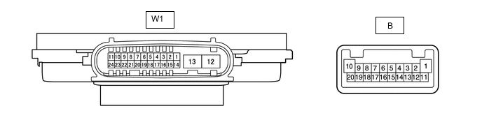
Terminal No. (Symbol) Wiring Color Terminal Description Condition Specified Condition W1-4 (IG) - Body ground B - Body ground Ignition power supply Power switch off Below 1 V Power switch on (IG) 11 to 14 V W1-12 (GND) - Body ground W-B - Body ground Ground Always Below 1 Ω W1-13 (ECUB) - Body ground W - Body ground Auxiliary battery power supply Power switch off and light control switch off Below 1 V Power switch on (IG) or light control switch in tail or head position 11 to 14 V -
Connect the W1 No. 1 headlight ECU sub-assembly LH connector.
Tech Tips
-
Since the W1 No. 1 headlight ECU sub-assembly LH connector is a waterproof type connector, the voltage and pulses cannot be checked directly. The values listed are for reference only.
-
Since the B No. 1 headlight ECU sub-assembly LH connector is a connected inside the headlight assembly, the voltage and pulses cannot be checked directly. The values listed are for reference only.
-
-
Measure the voltage and check of pulses according to the value(s) in the table below.
Terminal No. (Symbol) Wiring Color Terminal Description Condition Specified Condition W1-8 (RLD2) - Body ground G - Body ground Daytime running light/clearance light drive output Daytime running light or clearance light on Below 1 V Daytime running light and clearance light off Pulse generation W1-11 (TNS) - Body ground G - Body ground LH turn signal light signal input Power switch on (IG), LH turn signal light off Below 1 V Power switch on (IG), LH turn signal light blinking 11 to 14 V ←→ Below 1 V W1-16 (SBR) - W1-15 (SGR) GR - LG Rear height control sensor power supply Power switch on (IG) 4.75 to 5.25 V W1-17 (SHRL) - W1-15 (SGR) G - LG Rear height control sensor signal input Power switch on (IG), vehicle unloaded, vehicle stopped Approximately 2.5 V
(Value decreases as the front of the vehicle is raised)
W1-20 (LINL) - Body ground LG - Body ground LIN communication Power switch off Below 1 V Power switch on (IG) Pulse generation W1-23 (CANL) - Body ground B - Body ground CAN communication Power switch off Below 1 V Power switch on (IG) Pulse generation W1-24 (CANH) - Body ground V - Body ground CAN communication Power switch off Below 1 V Power switch on (IG) Pulse generation B-1 (HI-) - B-10 (HI+) - High beam headlights drive output High beam headlights off Below 1 V High beam headlights on 11 to 14 V B-4 (LOLED2) - B-5 (LOLED1) - Low beam headlights/high beam headlights drive output Low beam headlights and high beam headlights off Below 1 V Low beam headlights or high beam headlights on 11.2 to 17.7 V B-6 (FANB) - B-14 (FANG) - Headlight fan power source Low beam headlights off Below 1 V Low beam headlights on 4.5 to 5.5 V B-7 (ACTBI) - B-17 (ACTGI) - Headlight leveling motor power source Power switch off Below 1 V Power switch on (IG) 11 to 14 V B-8 (ACTSI) - B-17 (ACTGI) - Headlight leveling motor signal output Power switch on (IG), low beam headlights on, vehicle height not changed Below 1 V Power switch on (IG), low beam headlights on, vehicle height changed and maintained for more than 3 seconds 1.0 to 14 V B-9 (TURN+) - B-13 (TURN-) - Left turn signal light signal output Power switch on (IG), left turn signal light off Below 1 V Power switch on (IG), left turn signal light blinking 11 to 14 V ←→ Below 1 V B-15 (FANP) - B-14 (FANG) - Headlight fan control signal input Low beam headlights off Below 1 V Low beam headlights on Pulse generation
-
-
CHECK NO. 1 HEADLIGHT ECU SUB-ASSEMBLY LH (for LED Type Turn Signal Light)
-
Disconnect the W1 No. 1 headlight ECU sub-assembly LH connector.
-
Measure the voltage and resistance on the wire harness side connector according to the value(s) in the table below.
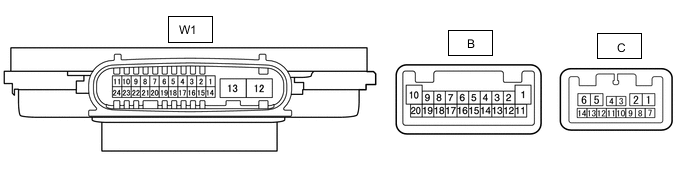
Terminal No. (Symbol) Wiring Color Terminal Description Condition Specified Condition W1-4 (IG) - Body ground B - Body ground Ignition power supply Power switch off Below 1 V Power switch on (IG) 11 to 14 V W1-12 (GND) - Body ground W-B - Body ground Ground Always Below 1 Ω W1-13 (ECUB) - Body ground W - Body ground Auxiliary battery power supply Power switch off and light control switch off Below 1 V Power switch on (IG) or light control switch in tail or head position 11 to 14 V -
Connect the W1 No. 1 headlight ECU sub-assembly LH connector.
Tech Tips
-
Since the W1 No. 1 headlight ECU sub-assembly LH connector is a waterproof type connector, the voltage and pulses cannot be checked directly. The values listed are for reference only.
-
Since the B and C No. 1 headlight ECU sub-assembly LH connectors are connected inside the headlight assembly, the voltage and pulses cannot be checked directly. The values listed are for reference only.
-
-
Measure the voltage and check of pulses according to the value(s) in the table below.
Terminal No. (Symbol) Wiring Color Terminal Description Condition Specified Condition W1-8 (RLD2) - Body ground G - Body ground Daytime running light/clearance light drive output Daytime running light or clearance light on Below 1 V Daytime running light and clearance light off Pulse generation W1-11 (TNS) - Body ground G - Body ground LH turn signal light signal input Power switch on (IG), LH turn signal light off Below 1 V Power switch on (IG), LH turn signal light blinking 11 to 14 V ←→ Below 1 V W1-16 (SBR) - W1-15 (SGR) GR - LG Rear height control sensor power supply Power switch on (IG) 4.75 to 5.25 V W1-17 (SHRL) - W1-15 (SGR) G - LG Rear height control sensor signal input Power switch on (IG), vehicle unloaded, vehicle stopped Approximately 2.5 V
(Value decreases as the front of the vehicle is raised)
W1-20 (LINL) - Body ground LG - Body ground LIN communication Power switch off Below 1 V Power switch on (IG) Pulse generation W1-23 (CANL) - Body ground B - Body ground CAN communication Power switch off Below 1 V Power switch on (IG) Pulse generation W1-24 (CANH) - Body ground V - Body ground CAN communication Power switch off Below 1 V Power switch on (IG) Pulse generation B-4 (LOLED2) - B-5 (LOLED1) - Low beam headlights drive output Low beam headlights off Below 1 V Low beam headlights on 16 to 25.7 V B-6 (FANB) - B-14 (FANG) - Headlight fan power source Low beam headlights off Below 1 V Low beam headlights on 4.5 to 5.5 V B-7 (ACTBI) - B-17 (ACTGI) - Headlight leveling motor power source Power switch off Below 1 V Power switch on (IG) 11 to 14 V B-8 (ACTSI) - B-17 (ACTGI) - Headlight leveling motor signal output Power switch on (IG), low beam headlights on, vehicle height not changed Below 1 V Power switch on (IG), low beam headlights on, vehicle height changed and maintained for more than 3 seconds 1.0 to 14 V B-9 (TURN+) - B-13 (TURN-) - Left turn signal light signal output Power switch on (IG), left turn signal light off Below 1 V Power switch on (IG), left turn signal light blinking 11 to 14 V ←→ Below 1 V B-15 (FANP) - B-14 (FANG) - Headlight fan control signal input Low beam headlights off Below 1 V Low beam headlights on Pulse generation C-8 (HILED2) - C-9 (HILED1) - High beam headlights drive output High beam headlights off Below 1 V High beam headlights on 11 to 14 V
-
-
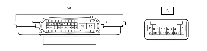
CHECK NO. 1 HEADLIGHT ECU SUB-ASSEMBLY RH (for Bulb Type Turn Signal Light)
-
Disconnect the G1 No. 1 headlight ECU sub-assembly RH connector.
-
Measure the voltage and resistance on the wire harness side connector according to the value(s) in the table below.
Terminal No. (Symbol) Wiring Color Terminal Description Condition Specified Condition G1-4 (IG) - Body ground B - Body ground Ignition power supply Power switch off Below 1 V Power switch on (IG) 11 to 14 V G1-12 (GND) - Body ground W-B - Body ground Ground Always Below 1 Ω G1-13 (ECUB) - Body ground G - Body ground Auxiliary battery power supply Power switch off and light control switch off Below 1 V Power switch on (IG) or light control switch in tail or head position 11 to 14 V -
Connect the G1 No. 1 headlight ECU sub-assembly RH connector.
Tech Tips
-
Since the G1 No. 1 headlight ECU sub-assembly RH connector is a waterproof type connector, the voltage and pulses cannot be checked directly. The values listed are for reference only.
-
Since the B No. 1 headlight ECU sub-assembly RH connector is a connected inside the headlight assembly, the voltage and pulses cannot be checked directly. The values listed are for reference only.
-
-
Measure the voltage and check of pulses according to the value(s) in the table below.
Terminal No.(Symbol) Wiring Color Terminal Description Condition Specified Condition G1-8 (RLD2) - Body ground G - Body ground Daytime running light/clearance light drive output Daytime running light or clearance light on Below 1 V Daytime running light and clearance light off Pulse generation G1-11 (TNS) - Body ground R - Body ground RH turn signal light signal input Power switch on (IG), RH turn signal light off Below 1 V Power switch on (IG), RH turn signal light blinking 11 to 14 V ←→ Below 1 V G1-20 (LINL) - Body ground LG - Body ground LIN communication Power switch off Below 1 V Power switch on (IG) Pulse generation B-1 (HI-) - B-10 (HI+) - High beam headlights drive output High beam headlights off Below 1 V High beam headlights on 11 to 14 V B-4 (LOLED2) - B-5 (LOLED1) - Low beam headlights/high beam headlights drive output Low beam headlights and high beam headlights off Below 1 V Low beam headlights or high beam headlights on 11.2 to 17.7 V B-6 (FANB) - B-14 (FANG) - Headlight fan power source Low beam headlights off Below 1 V Low beam headlights on 4.5 to 5.5 V B-7 (ACTBI) - B-17 (ACTGI) - Headlight leveling motor power source Power switch off Below 1 V Power switch on (IG) 11 to 14 V B-8 (ACTSI) - B-17 (ACTGI) - Headlight leveling motor signal output Power switch on (IG), low beam headlights on, vehicle height not changed Below 1 V Power switch on (IG), low beam headlights on, vehicle height changed and maintained for more than 3 seconds 1.0 to 14 V B-9 (TURN+) - B-13 (TURN-) - Right turn signal light signal output Power switch on (IG), right turn signal light off Below 1 V Power switch on (IG), right turn signal light blinking 11 to 14 V ←→ Below 1 V B-15 (FANP) - B-14 (FANG) - Headlight fan control signal input Low beam headlights off Below 1 V Low beam headlights on Pulse generation
-
-
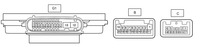
CHECK NO. 1 HEADLIGHT ECU SUB-ASSEMBLY RH (for LED Type Turn Signal Light)
-
Disconnect the G1 No. 1 headlight ECU sub-assembly RH connector.
-
Measure the voltage and resistance on the wire harness side connector according to the value(s) in the table below.
Terminal No.(Symbol) Wiring Color Terminal Description Condition Specified Condition G1-4 (IG) - Body ground B - Body ground Ignition power supply Power switch off Below 1 V Power switch on (IG) 11 to 14 V G1-12 (GND) - Body ground W-B - Body ground Ground Always Below 1 Ω G1-13 (ECUB) - Body ground G - Body ground Auxiliary battery power supply Power switch off and light control switch off Below 1 V Power switch on (IG) or light control switch in tail or head position 11 to 14 V -
Connect the G1 No. 1 headlight ECU sub-assembly RH connector.
Tech Tips
-
Since the G1 No. 1 headlight ECU sub-assembly RH connector is a waterproof type connector, the voltage and pulses cannot be checked directly. The values listed are for reference only.
-
Since the B and C No. 1 headlight ECU sub-assembly RH connectors are connected inside the headlight assembly, the voltage and pulses cannot be checked directly. The values listed are for reference only.
-
-
Measure the voltage and check of pulses according to the value(s) in the table below.
Terminal No.(Symbol) Wiring Color Terminal Description Condition Specified Condition G1-8 (RLD2) - Body ground G - Body ground Daytime running light/clearance light drive output Daytime running light or clearance light on Below 1 V Daytime running light and clearance light off Pulse generation G1-11 (TNS) - Body ground R - Body ground RH turn signal light signal input Power switch on (IG), RH turn signal light off Below 1 V Power switch on (IG), RH turn signal light blinking 11 to 14 V ←→ Below 1 V G1-20 (LINL) - Body ground LG - Body ground LIN communication Power switch off Below 1 V Power switch on (IG) Pulse generation B-4 (LOLED2) - B-5 (LOLED1) - Low beam headlights drive output Low beam headlights off Below 1 V Low beam headlights on 16 to 25.7 V B-6 (FANB) - B-14 (FANG) - Headlight fan power source Low beam headlights off Below 1 V Low beam headlights on 4.5 to 5.5 V B-7 (ACTBI) - B-17 (ACTGI) - Headlight leveling motor power source Power switch off Below 1 V Power switch on (IG) 11 to 14 V B-8 (ACTSI) - B-17 (ACTGI) - Headlight leveling motor signal output Power switch on (IG), low beam headlights on, vehicle height not changed Below 1 V Power switch on (IG), low beam headlights on, vehicle height changed and maintained for more than 3 seconds 1.0 to 14 V B-9 (TURN+) - B-13 (TURN-) - Right turn signal light signal output Power switch on (IG), right turn signal light off Below 1 V Power switch on (IG), right turn signal light blinking 11 to 14 V ←→ Below 1 V B-15 (FANP) - B-14 (FANG) - Headlight fan control signal input Low beam headlights off Below 1 V Low beam headlights on Pulse generation C-8 (HILED2) - C-9 (HILED1) - High beam headlights drive output High beam headlights off Below 1 V High beam headlights on 11 to 14 V
-
-
CHECK COMBINATION METER ASSEMBLY
-
CHECK OUTER MIRROR CONTROL ECU ASSEMBLY LH (for Power Mirror Control System (w/ Memory))
-
CHECK OUTER MIRROR CONTROL ECU ASSEMBLY RH (for Power Mirror Control System (w/ Memory))