OUTER REAR VIEW MIRROR INSTALLATION
CAUTION / NOTICE / HINT
Tech Tips
-
Use the same procedure for the LH side and RH side.
-
The following procedure is for the LH side.
PROCEDURE
-
INSTALL OUTER REAR VIEW MIRROR ASSEMBLY
-
Engage the claw to temporarily install the outer rear view mirror assembly.
-
Install the outer rear view mirror assembly with the 3 nuts.
- Torque:
- 5.5 N*m { 56 kgf*cm, 49 in.*lbf }
-
Engage the clamp.
-
w/o Memory:
-
Connect the connector.
-
-
-
INSTALL OUTER MIRROR INSTALL HOLE COVER
-
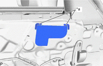
*a Reference Point Install a new outer mirror install hole cover while aligning it to the reference points on the front door panel.
Note
Securely install the outer mirror install hole cover preventing wrinkles and air bubbles.
-
-
INSTALL OUTER MIRROR PROTECTOR
-
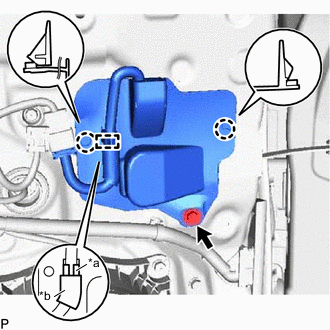
*a Clamp *b Seal Engage the 2 claws to temporarily install the outer mirror protector.
-
Install the outer mirror protector with the screw.
- Torque:
- 1.75 N*m { 18 kgf*cm, 15 in.*lbf }
-
Engage the clamp to connect the wire harness as shown in the illustration.
-
-
INSTALL OUTER MIRROR CONTROL ECU ASSEMBLY (w/ Memory)
-
INSTALL FRONT DOOR INNER GLASS WEATHERSTRIP
-
INSTALL FRONT DOOR TRIM BOARD SUB-ASSEMBLY
-
INSTALL FRONT DOOR NO. 1 STIFFENER CUSHION
-
INSTALL COURTESY LIGHT ASSEMBLY
-
INSTALL FRONT DOOR ARMREST COVER
-
INSTALL MULTIPLEX NETWORK MASTER SWITCH ASSEMBLY WITH FRONT DOOR ARMREST BASE PANEL (for Driver Side)
-
INSTALL POWER WINDOW REGULATOR SWITCH ASSEMBLY WITH FRONT DOOR ARMREST BASE PANEL (for Front Passenger Side)
-
INSTALL FRONT DOOR INSIDE HANDLE BEZEL PLUG
-
CONNECT CABLE TO NEGATIVE AUXILIARY BATTERY TERMINAL
Note
When disconnecting the cable, some systems need to be initialized after the cable is reconnected.
-
INSTALL BATTERY SERVICE HOLE COVER LH