POWER MIRROR CONTROL SYSTEM(w/ Memory) Power Mirrors do not Return to Memorized Position
DESCRIPTION
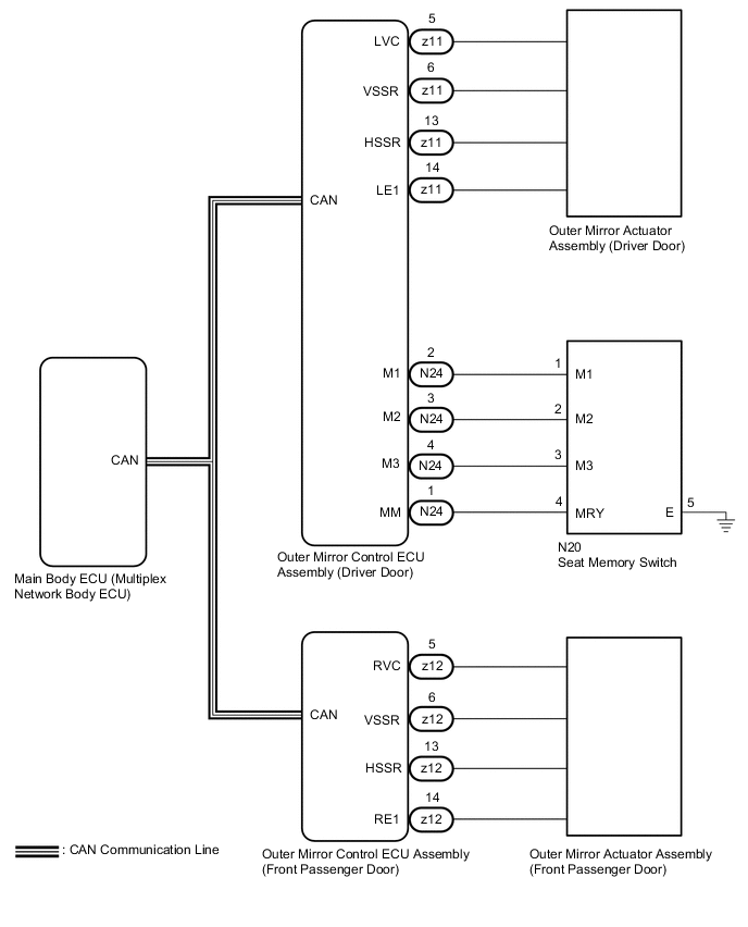
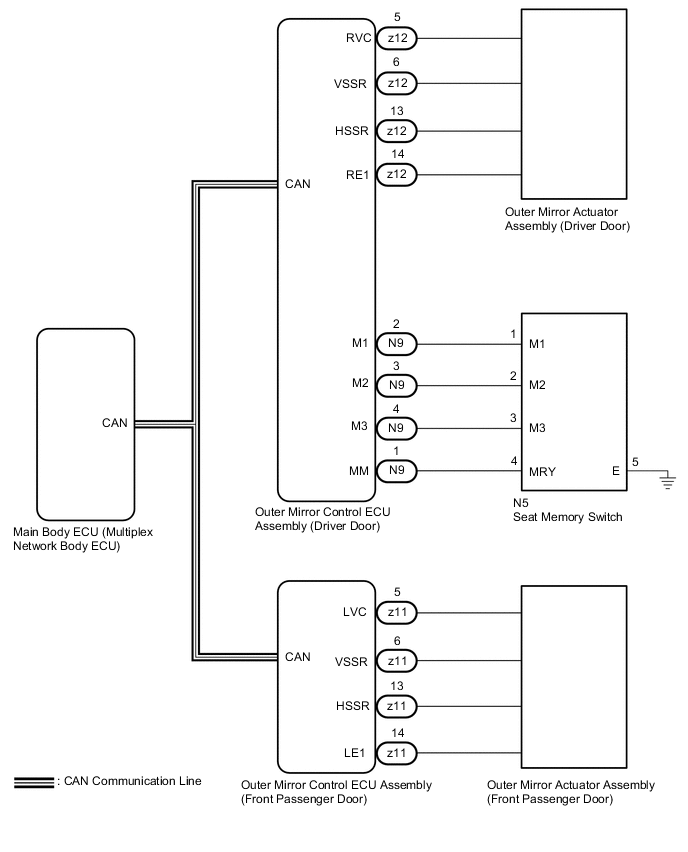
If any of the M1, M2 or M3 seat memory switch is pressed, the outer mirror control ECU assembly (driver door) detects the switch operation and sends the seat memory switch signal to the main body ECU (multiplex network body ECU) via CAN communication. The main body ECU (multiplex network body ECU) sends the reproduction signal to each outer mirror control ECU assembly via CAN communication. When receiving the reproduction signal, each outer mirror control ECU assembly operates the vertical and horizontal mirror motors, which are built into the outer rear view mirror assembly, to adjust the mirror surface to the stored position.
WIRING DIAGRAM
-
for LHD
-
for RHD
CAUTION / NOTICE / HINT
Note
-
The power mirror control system (w/ Memory) uses the CAN communication system. First, confirm that there is no malfunction in the CAN communication system. Refer to the How to Proceed with Troubleshooting procedure.
-
Before replacing the main body ECU (multiplex network body ECU), refer to Service Bulletin.
PROCEDURE
-
CHECK SEAT MEMORY SWITCH FUNCTION
-
When any seat memory switch (M1, M2 or M3) is pressed, check that the driver seat moves to the memorized position.
OK Driver seat moves to the memorized position. Result Proceed to OK NG
NG 
GO TO FRONT POWER SEAT CONTROL SYSTEM (Power Seat does not Return to Memorized Position) Click here
OK 
-
-
CHECK ELECTRICAL REMOTE CONTROL MIRROR FUNCTION
-
Check the electrical remote control mirror function.
OK Electrical remote control mirror function is normal. Result Proceed to OK NG
NG
GO TO OTHER DIAGNOSIS PROCEDURE (Power Mirror cannot be Adjusted with Power Mirror Switch) Click here
OK
-
-
READ VALUE USING GTS
-
Connect the GTS to the DLC3.
-
Turn the power switch on (IG).
-
Turn the GTS on.
-
Enter the following menus: Body Electrical / Mirror L or Mirror R / Data List.
-
Read the Data List according to the display on the GTS.
Body Electrical > Mirror L > Data ListTester Display Measurement Item Range Normal Condition Diagnostic Note Mirror Memory No.1 Mirror position memorized in memory switch M1 OFF or ON OFF: Not memorized
ON: Memorized
- Mirror Memory No.2 Mirror position memorized in memory switch M2 OFF or ON OFF: Not memorized
ON: Memorized
- Mirror Memory No.3 Mirror position memorized in memory switch M3 OFF or ON OFF: Not memorized
ON: Memorized
-
Body Electrical > Mirror L > Data ListTester Display Mirror Memory No.1 Mirror Memory No.2 Mirror Memory No.3
Body Electrical > Mirror R > Data ListTester Display Measurement Item Range Normal Condition Diagnostic Note Mirror Memory No.1 Mirror position memorized in memory switch M1 OFF or ON OFF: Not memorized
ON: Memorized
- Mirror Memory No.2 Mirror position memorized in memory switch M2 OFF or ON OFF: Not memorized
ON: Memorized
- Mirror Memory No.3 Mirror position memorized in memory switch M3 OFF or ON OFF: Not memorized
ON: Memorized
-
Body Electrical > Mirror R > Data ListTester Display Mirror Memory No.1 Mirror Memory No.2 Mirror Memory No.3 OK ON (Memorized) appears on the screen. Result Proceed to OK NG
NG
GO TO OTHER DIAGNOSIS PROCEDURE (Power Mirror Surface Position is not Memorized) Click here
OK
-
-
CHECK MEMORY AND REACTIVATION FUNCTION
-
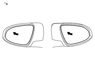
*a Turn to Fully Left Position Turn the power switch on (IG).
-
Using the multiplex network master switch assembly, turn the mirror surface to the fully left position.
-
Press the M1 switch while the SET switch is being pressed.
-
Check that the buzzer sounds for 0.5 seconds and the mirror surface position is memorized.
-
Using the multiplex network master switch assembly, turn the mirror surface to the fully right position.
-
Press the M1 switch.
-
Check that the buzzer sounds for 0.1 seconds and the outer mirror automatically moves to the memorized fully left position.
Result Result Proceed to Memory and reactivation functions on both mirrors are not normal A Memory and reactivation function on driver door mirror is not normal B Memory and reactivation function on front passenger door mirror is not normal C
A
REPLACE MAIN BODY ECU (MULTIPLEX NETWORK BODY ECU) Click here
C 
REPLACE OUTER MIRROR ACTUATOR ASSEMBLY (FRONT PASSENGER DOOR) Click here
B
-
-
REPLACE OUTER MIRROR ACTUATOR ASSEMBLY (DRIVER DOOR)
-
Temporarily replace the outer mirror actuator assembly (driver door) with a new or known good one.
Result Proceed to NEXT
NEXT
-
-
CHECK MEMORY AND REACTIVATION FUNCTION
-
*a Turn to Fully Left Position Turn the power switch on (IG).
-
Using the multiplex network master switch assembly, turn the mirror surface to the fully left position.
-
Press the M1 switch while the SET switch is being pressed.
-
Check that the buzzer sounds for 0.5 seconds and the mirror surface position is memorized.
-
Using the multiplex network master switch assembly, turn the mirror surface to the fully right position.
-
Press the M1 switch.
-
Check that the buzzer sounds for 0.1 seconds and the outer mirror automatically moves to the memorized fully left position.
Result Proceed to OK NG
OK
END (OUTER MIRROR ACTUATOR ASSEMBLY (DRIVER DOOR) WAS DEFECTIVE)
NG
REPLACE OUTER MIRROR CONTROL ECU ASSEMBLY (DRIVER DOOR) Click here
-
-
REPLACE OUTER MIRROR ACTUATOR ASSEMBLY (FRONT PASSENGER DOOR)
-
Temporarily replace the outer mirror actuator assembly (front passenger door) with a new or known good one.
Result Proceed to NEXT
NEXT
-
-
CHECK MEMORY AND REACTIVATION FUNCTION
-
*a Turn to Fully Left Position Turn the power switch on (IG).
-
Using the multiplex network master switch assembly, turn the mirror surface to the fully left position.
-
Press the M1 switch while the SET switch is being pressed.
-
Check that the buzzer sounds for 0.5 seconds and the mirror surface position is memorized.
-
Using the multiplex network master switch assembly, turn the mirror surface to the fully right position.
-
Press the M1 switch.
-
Check that the buzzer sounds for 0.1 seconds and the outer mirror automatically moves to the memorized fully left position.
Result Proceed to OK NG
OK
END (OUTER MIRROR ACTUATOR ASSEMBLY (FRONT PASSENGER DOOR) WAS DEFECTIVE)
NG
REPLACE OUTER MIRROR CONTROL ECU ASSEMBLY (FRONT PASSENGER DOOR) Click here
-