TRIP SWITCH INSPECTION
PROCEDURE
-
INSPECT TRIP SWITCH (for LHD)
-
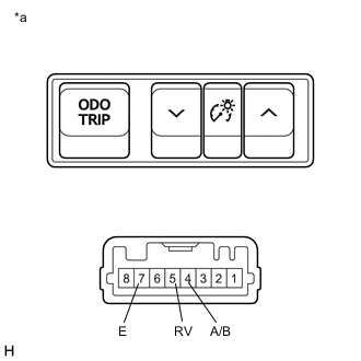
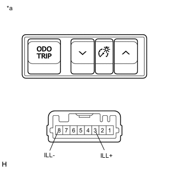
*a Component without harness connected
(Trip Switch)
Measure the resistance according to the value(s) in the table below.
Standard Resistance Tester Connection Condition Specified Condition 5 (RV) - 7 (E) Light control rheostat up switch pressed Below 1 Ω Light control rheostat up switch not pressed 10 kΩ or higher 5 (RV) - 7 (E) Light control rheostat down switch pressed 1.71 to 1.89 kΩ Light control rheostat down switch not pressed 10 kΩ or higher 4 (A/B) - 7 (E) ODO/TRIP switch pressed Below 1 Ω ODO/TRIP switch not pressed 10 kΩ or higher If the result is not as specified, replace the trip switch.
-
*a Component without harness connected
(Trip Switch)
Illumination Inspection
-
Apply auxiliary battery voltage to the trip switch and check that it illuminates.
OK Condition Specified Condition Auxiliary battery positive (+) → Terminal 3 (ILL+)
Auxiliary battery negative (-) → Terminal 8 (ILL-)
Illuminates If the result is not as specified, replace the trip switch.
-
-
-
INSPECT TRIP SWITCH (for RHD)
-
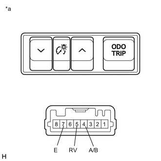
*a Component without harness connected
(Trip Switch)
Measure the resistance according to the value(s) in the table below.
Standard Resistance Tester Connection Condition Specified Condition 5 (RV) - 7 (E) Light control rheostat up switch pressed Below 1 Ω Light control rheostat up switch not pressed 10 kΩ or higher 5 (RV) - 7 (E) Light control rheostat down switch pressed 1.71 to 1.89 kΩ Light control rheostat down switch not pressed 10 kΩ or higher 4 (A/B) - 7 (E) ODO/TRIP switch pressed Below 1 Ω ODO/TRIP switch not pressed 10 kΩ or higher If the result is not as specified, replace the trip switch.
-
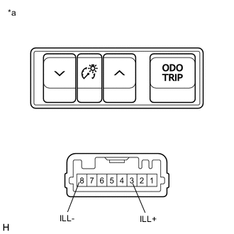
*a Component without harness connected
(Trip Switch)
Illumination Inspection
-
Apply auxiliary battery voltage to the trip switch and check that it illuminates.
OK Condition Specified Condition Auxiliary battery positive (+) → Terminal 3 (ILL+)
Auxiliary battery negative (-) → Terminal 8 (ILL-)
Illuminates If the result is not as specified, replace the trip switch.
-
-