COMBINATION METER REMOVAL
PROCEDURE
-
PRECAUTION
Note
After turning the power switch off, waiting time may be required before disconnecting the cable from the negative (-) auxiliary battery terminal. Therefore, make sure to read the disconnecting the cable from the negative (-) auxiliary battery terminal notice before proceeding with work.
-
CUSTOMIZE POWER TILT AND POWER TELESCOPIC STEERING COLUMN SYSTEM (for Power Tilt and Power Telescopic Steering Column)
-
REMOVE BATTERY SERVICE HOLE COVER LH
-
DISCONNECT CABLE FROM NEGATIVE AUXILIARY BATTERY TERMINAL
Note
When disconnecting the cable, some systems need to be initialized after the cable is reconnected.
-
REMOVE NO. 1 INSTRUMENT PANEL UNDER COVER SUB-ASSEMBLY
-
DISCONNECT HOOD LOCK CONTROL LEVER SUB-ASSEMBLY
-
REMOVE LOWER INSTRUMENT PANEL FINISH PANEL SUB-ASSEMBLY
-
REMOVE METER HOOD SUB-ASSEMBLY
-
REMOVE COMBINATION METER ASSEMBLY
-
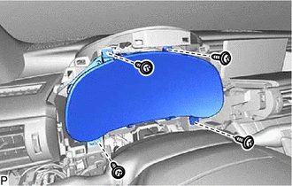
Remove the 4 screws.
-
for Standard:
-
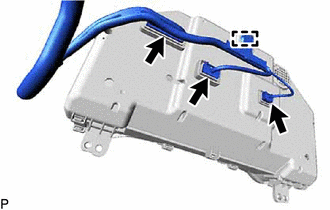
Disengage the clamp.
-
Disconnect each connector to remove the combination meter assembly.
-
-
for Sport Package:
-
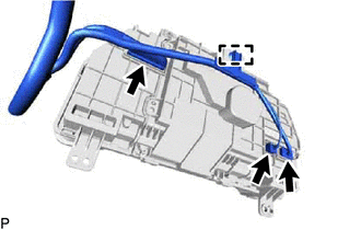
Disengage the clamp.
-
Disconnect each connector to remove the combination meter assembly.
-
-