METER / GAUGE SYSTEM Meter Illumination does not Dim at Night
DESCRIPTION
In this circuit, the combination meter assembly receives auto dimmer signals from the main body ECU (multiplex network body ECU) via the CAN communication system. When the combination meter assembly receives an auto dimmer signal, it dims the meter illumination (warning and indicator lights).
The main body ECU (multiplex network body ECU) determines whether it is daytime or nighttime based on the waveform transmitted from the automatic light control sensor. If the main body ECU (multiplex network body ECU) determines that it is nighttime and the headlight dimmer switch assembly is in the tail, head, or AUTO position, the ECU sends an auto dimmer signal to the combination meter assembly.
According to this signal, the combination meter assembly dims the meter illumination.
Tech Tips
When the meter illumination does not dim at night, there may be a malfunction in the automatic light control sensor, main body ECU (multiplex network body ECU), CAN communication system, wire harness, connector, or combination meter assembly.
WIRING DIAGRAM
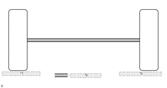
| *1 | Main Body ECU (Multiplex Network Body ECU) |
| *2 | CAN Communication Line |
| *3 | Combination Meter Assembly (Meter Circuit Plate) |
CAUTION / NOTICE / HINT
Tech Tips
-
The automatic light control sensor sensitivity can be customized.
-
Setting the meter illumination to maximum brightness prevents the meter illumination from dimming when the headlight dimmer switch assembly is changed to the tail, head, or AUTO position at night. Therefore, check the meter illumination setting before proceeding to the following steps.
-
Before starting the following inspection, check if lighting system DTCs are output.
PROCEDURE
-
CHECK CAN COMMUNICATION SYSTEM
-
Check if CAN communication DTCs are output.
Result Result Proceed to CAN communication DTCs are not output. A CAN communication DTCs are output. B
B 
GO TO CAN COMMUNICATION SYSTEM Click here
A 
-
-
READ VALUE USING GTS (LIGHT SENSOR ILLUMINANCE)
-
Connect the GTS to the DLC3.
-
Turn the power switch on (IG).
-
Turn the GTS on.
-
Enter the following menus: Body Electrical / Main Body / Data List.
-
Check the values by referring to the table below.
Body Electrical > Main Body > Data ListTester Display Measurement Item Range Normal Condition Diagnostic Note Light Sensor Illuminance Light sensor illuminance 0 lx to 8191 lx Value output according to ambient light levels -
Body Electrical > Main Body > Data ListTester Display Light Sensor Illuminance Result Result Proceed to The output value changes according to the ambient light level. A The output value does not change according to the ambient light level. B
B
CHECK CUSTOMIZE PARAMETER SETTING (SENSITIVITY) Click here
A
-
-
REPLACE MAIN BODY ECU (MULTIPLEX NETWORK BODY ECU)
-
Replace the main body ECU (multiplex network body ECU) with a new or known good one.
OK The operation of the combination meter assembly returns to normal. Tech Tips
The combination meter assembly controls the meter illumination based on an auto dimmer signal from the main body ECU (multiplex network body ECU). If the combination meter assembly does not dim when the headlight dimmer switch assembly is in the tail, head, or AUTO position at night, it may be for one of 2 reasons. The first reason is that the main body ECU (multiplex network body ECU) did not send an auto dimmer signal. The second is that the combination meter assembly did not dim the meter illumination even though the combination meter assembly received an auto dimmer signal.
Result Proceed to OK NG
OK
END
NG
REPLACE COMBINATION METER ASSEMBLY Click here
-