METER / GAUGE SYSTEM, Diagnostic DTC:B1507
| DTC Code | DTC Name |
|---|---|
| B1507 | Open in Turn Signal Circuit |
DESCRIPTION
This DTC is stored when the combination meter assembly (meter circuit plate) detects an open in a turn signal light circuit.
Tech Tips
-
If there is an open in a front turn signal light circuit or rear turn signal light circuit, the turn signal lights on the side with the open circuit will blink faster than usual.
-
If there is an open in a side turn signal light circuit, DTC B1507 will not be stored.
| DTC No. | Detection Item | DTC Detection Condition | Trouble Area | Memory |
|---|---|---|---|---|
| B1507 | Open in Turn Signal Circuit | Diagnosis Condition:
Malfunction Status:
|
|
DTC stored |
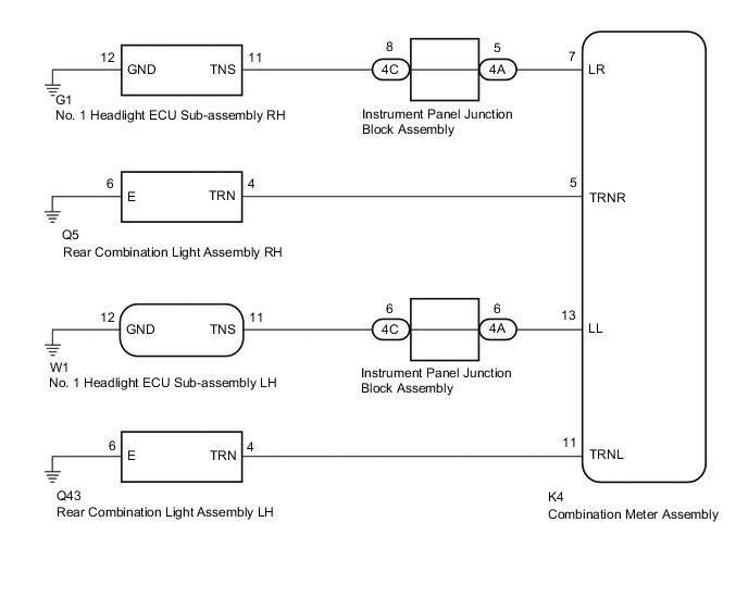
WIRING DIAGRAM
CAUTION / NOTICE / HINT
Note
Inspect the bulbs for this system before performing the following procedure.
Front turn signal light assembly (for LED Type Turn Signal Light): Click here
Front turn signal light assembly (for bulb Type Turn Signal Light): Click here
Rear turn signal light assembly: Click here
PROCEDURE
-
INSPECT LIGHTS
-
Inspect the illumination of each turn signal light.
Result Result Proceed to Front turn signal light LH does not blink A Rear turn signal light LH does not blink B Front turn signal light RH does not blink C Rear turn signal light RH does not blink D
B 
CHECK HARNESS AND CONNECTOR (REAR COMBINATION LIGHT ASSEMBLY LH - COMBINATION METER ASSEMBLY OR BODY GROUND) Click here
C
CHECK HARNESS AND CONNECTOR (INSTRUMENT PANEL JUNCTION BLOCK ASSEMBLY - COMBINATION METER ASSEMBLY) Click here
D
CHECK HARNESS AND CONNECTOR (REAR COMBINATION LIGHT ASSEMBLY RH - COMBINATION METER ASSEMBLY OR BODY GROUND) Click here
A 
-
-
CHECK HARNESS AND CONNECTOR (INSTRUMENT PANEL JUNCTION BLOCK ASSEMBLY - COMBINATION METER ASSEMBLY)
-
Disconnect the 4A instrument panel junction block assembly connector.
-
Disconnect the K4 combination meter assembly connector.
-
Measure the resistance according to the value(s) in the table below.
Standard Resistance Tester Connection Condition Specified Condition 4A-6 - K4-13 (LL) Always Below 1 Ω Result Proceed to OK NG
NG 
REPAIR OR REPLACE HARNESS OR CONNECTOR
OK
-
-
CHECK HARNESS AND CONNECTOR (NO. 1 HEADLIGHT ECU SUB-ASSEMBLY LH - INSTRUMENT PANEL JUNCTION BLOCK ASSEMBLY OR BODY GROUND)
-
Disconnect the W1 no. 1 headlight ECU sub-assembly LH connector.
-
Disconnect the 4C instrument panel junction block assembly connector.
-
Measure the resistance according to the value(s) in the table below.
Standard Resistance Tester Connection Condition Specified Condition W1-11 (TNS) - 4C-6 Always Below 1 Ω W1-12 (GND) - Body ground Always Below 1 Ω Result Proceed to OK NG
NG
REPAIR OR REPLACE HARNESS OR CONNECTOR
OK
-
-
INSPECT INSTRUMENT PANEL JUNCTION BLOCK ASSEMBLY
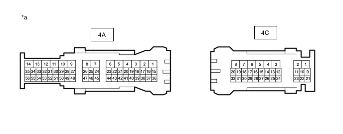
*a Component without harness connected
(Instrument Panel Junction Block Assembly)
- -
-
Measure the resistance according to the value(s) in the table below.
Standard Resistance Tester Connection Condition Specified Condition 4C-6 - 4A-6 Always Below 1 Ω Result Proceed to OK NG
OK
REPLACE COMBINATION METER ASSEMBLY Click here
NG
REPLACE INSTRUMENT PANEL JUNCTION BLOCK ASSEMBLY Click here
-
-
CHECK HARNESS AND CONNECTOR (REAR COMBINATION LIGHT ASSEMBLY LH - COMBINATION METER ASSEMBLY OR BODY GROUND)
-
Disconnect the Q43 rear combination light assembly LH connector.
-
Disconnect the K4 combination meter assembly connector.
-
Measure the resistance according to the value(s) in the table below.
Standard Resistance Tester Connection Condition Specified Condition Q43-4 (TRN) - K4-11 (TRNL) Always Below 1 Ω Q43-6 (E) - Body ground Always Below 1 Ω Result Proceed to OK NG
OK
REPLACE COMBINATION METER ASSEMBLY Click here
NG
REPAIR OR REPLACE HARNESS OR CONNECTOR
-
-
CHECK HARNESS AND CONNECTOR (INSTRUMENT PANEL JUNCTION BLOCK ASSEMBLY - COMBINATION METER ASSEMBLY)
-
Disconnect the 4A instrument panel junction block assembly connector.
-
Disconnect the K4 combination meter assembly connector.
-
Measure the resistance according to the value(s) in the table below.
Standard Resistance Tester Connection Condition Specified Condition 4A-5 - K4-7 (LR) Always Below 1 Ω Result Proceed to OK NG
NG
REPAIR OR REPLACE HARNESS OR CONNECTOR
OK
-
-
CHECK HARNESS AND CONNECTOR (NO. 1 HEADLIGHT ECU SUB-ASSEMBLY RH - INSTRUMENT PANEL JUNCTION BLOCK ASSEMBLY OR BODY GROUND)
-
Disconnect the G1 no. 1 headlight ECU sub-assembly RH connector.
-
Disconnect the 4C instrument panel junction block assembly connector.
-
Measure the resistance according to the value(s) in the table below.
Standard Resistance Tester Connection Condition Specified Condition G1-11 (TNS) - 4C-8 Always Below 1 Ω G1-12 (GND) - Body ground Always Below 1 Ω Result Proceed to OK NG
NG
REPAIR OR REPLACE HARNESS OR CONNECTOR
OK
-
-
INSPECT INSTRUMENT PANEL JUNCTION BLOCK ASSEMBLY
*a Component without harness connected
(Instrument Panel Junction Block Assembly)
- -
-
Measure the resistance according to the value(s) in the table below.
Standard Resistance Tester Connection Condition Specified Condition 3A-4 - 3F-8 Always Below 1 Ω Result Proceed to OK NG
OK
REPLACE COMBINATION METER ASSEMBLY Click here
NG
REPLACE INSTRUMENT PANEL JUNCTION BLOCK ASSEMBLY Click here
-
-
CHECK HARNESS AND CONNECTOR (REAR COMBINATION LIGHT ASSEMBLY RH - COMBINATION METER ASSEMBLY OR BODY GROUND)
-
Disconnect the Q5 rear combination light assembly RH connector.
-
Disconnect the I7 combination meter assembly connector.
-
Measure the resistance according to the value(s) in the table below.
Standard Resistance Tester Connection Condition Specified Condition Q5-4 (TRN) - K4-5 (TRNR) Always Below 1 Ω Q5-6 (E) - Body ground Always Below 1 Ω Result Proceed to OK NG
OK
REPLACE COMBINATION METER ASSEMBLY Click here
NG
REPAIR OR REPLACE HARNESS OR CONNECTOR
-