METER / GAUGE SYSTEM, Diagnostic DTC:B1508
| DTC Code | DTC Name |
|---|---|
| B1508 | Short in Turn Signal / Hazard Flasher Circuit |
DESCRIPTION
This DTC is stored when the combination meter assembly (meter circuit plate) detects an short in a turn signal light circuit.
Tech Tips
If there is a short in a turn signal light circuit, all of the turn signal lights on the side with the short circuit will not blink.
| DTC No. | Detection Item | DTC Detection Condition | Trouble Area | Memory |
|---|---|---|---|---|
| B1508 | Short in Turn Signal / Hazard Flasher Circuit | Diagnosis Condition:
Malfunction Status:
|
|
DTC stored |
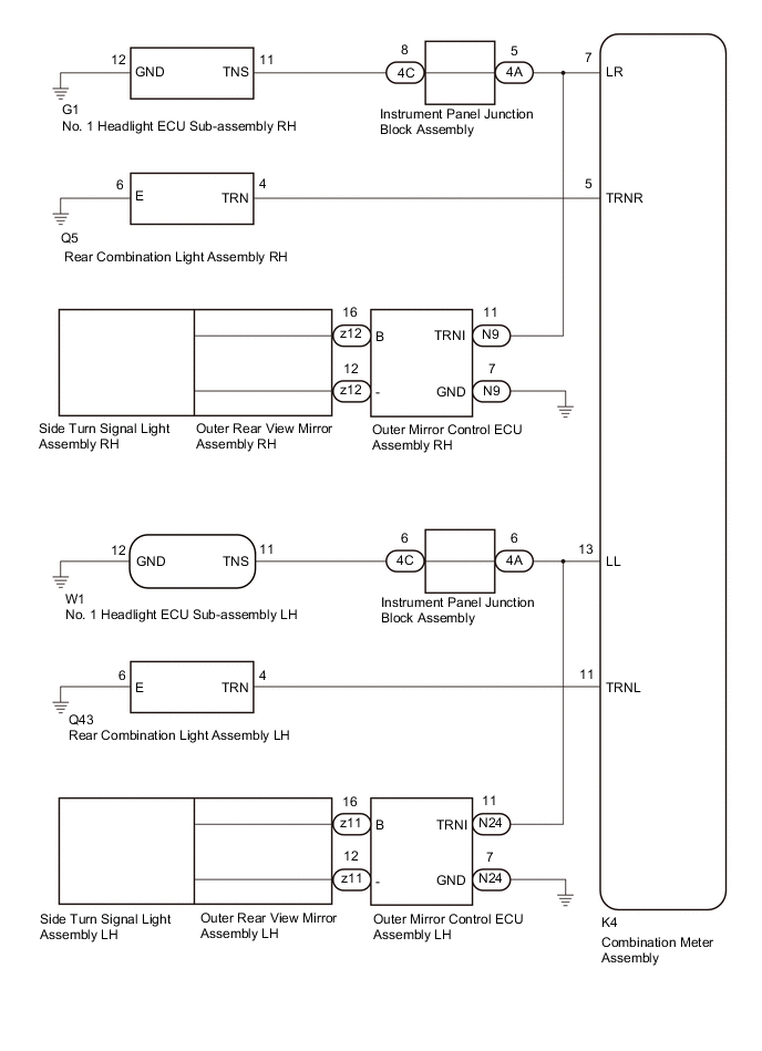
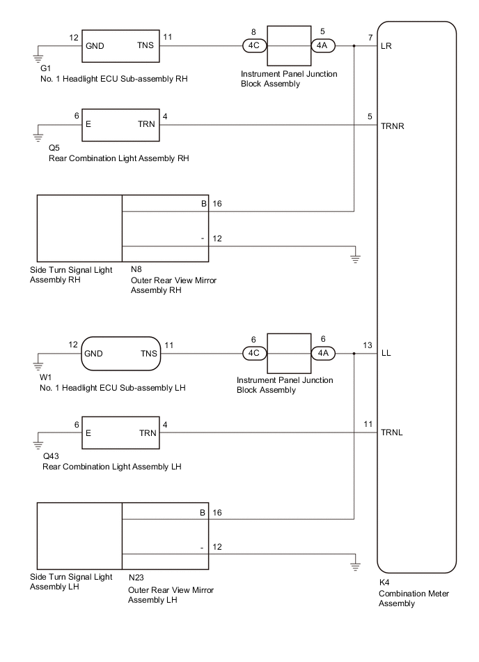
WIRING DIAGRAM
-
w/ Seat Position Memory
-
w/o Seat Position Memory
CAUTION / NOTICE / HINT
Note
Inspect the bulbs for this system before performing the following procedure.
Front turn signal light assembly (for LED Type Turn Signal Light): Click here
Front turn signal light assembly (for bulb Type Turn Signal Light): Click here
Rear turn signal light assembly: Click here
Side turn signal light assembly: Click here
PROCEDURE
-
INSPECT LIGHTS
-
Inspect the illumination of each turn signal light.
Result Result Proceed to All LH turn signal lights do not blink A All RH turn signal lights do not blink B
B 
CHECK HARNESS AND CONNECTOR (REAR COMBINATION LIGHT ASSEMBLY RH - COMBINATION METER ASSEMBLY) Click here
A 
-
-
CHECK HARNESS AND CONNECTOR (REAR COMBINATION LIGHT ASSEMBLY LH - COMBINATION METER ASSEMBLY)
-
Disconnect the Q43 rear combination light assembly LH connector.
-
Disconnect the K4 combination meter assembly connector.
-
Measure the resistance according to the value(s) in the table below.
Standard Resistance Tester Connection Condition Specified Condition Q43-4 (TRN) or K4-11 (TRNL) - Body ground Always 10 kΩ or higher Result Proceed to OK NG
NG 
REPAIR OR REPLACE HARNESS OR CONNECTOR
OK
-
-
CHECK HARNESS AND CONNECTOR (NO. 1 HEADLIGHT ECU SUB-ASSEMBLY LH - INSTRUMENT PANEL JUNCTION BLOCK ASSEMBLY)
-
Disconnect the W1 No. 1 headlight ECU sub-assembly LH connector.
-
Disconnect the 4C instrument panel junction block assembly connector.
-
Measure the resistance according to the value(s) in the table below.
Standard Resistance Tester Connection Condition Specified Condition W1-11 (TNS) or 4C-6 - Body ground Always 10 kΩ or higher Result Result Proceed to OK A NG B
B
REPAIR OR REPLACE HARNESS OR CONNECTOR
A
-
-
INSPECT INSTRUMENT PANEL JUNCTION BLOCK ASSEMBLY
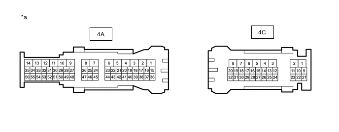
*a Component without harness connected
(Instrument Panel Junction Block Assembly)
- -
-
Measure the resistance according to the value(s) in the table below.
Note
Make sure to perform this step with the instrument panel junction block assembly installed to the vehicle.
Standard Resistance Tester Connection Condition Specified Condition 4C-6 or 4A-6 - Body ground Always 10 kΩ or higher Result Proceed to OK NG
NG
REPLACE INSTRUMENT PANEL JUNCTION BLOCK ASSEMBLY Click here
OK
-
-
CONFIRM MODEL
Result Result Proceed to w/ Seat Position Memory A w/o Seat Position Memory B
B
CHECK HARNESS AND CONNECTOR (INSTRUMENT PANEL JUNCTION BLOCK ASSEMBLY AND OUTER REAR VIEW MIRROR ASSEMBLY LH - COMBINATION METER ASSEMBLY) Click here
A
-
CHECK HARNESS AND CONNECTOR (INSTRUMENT PANEL JUNCTION BLOCK ASSEMBLY AND OUTER MIRROR CONTROL ECU ASSEMBLY LH - COMBINATION METER ASSEMBLY)
-
Disconnect the 4A instrument panel junction block assembly connector.
-
Disconnect the N24 outer mirror control ECU assembly LH connector.
-
Measure the resistance according to the value(s) in the table below.
Standard Resistance Tester Connection Condition Specified Condition 4A-6, N24-11(TRNI) or K4-13 (LL) - Body ground Always 10 kΩ or higher Result Proceed to OK NG
NG
REPAIR OR REPLACE HARNESS OR CONNECTOR
OK
-
-
INSPECT OUTER REAR VIEW MIRROR ASSEMBLY LH
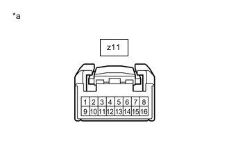
*a Component without harness connected
(Outer Rear View Mirror Assembly LH)
-
Remove the outer rear view mirror assembly LH.
-
Remove the side turn signal light assembly LH from the outer rear view mirror assembly LH.
-
Measure the resistance according to the value(s) in the table below.
Standard Resistance Tester Connection Condition Specified Condition z11-16 - z11-12 Always 10 kΩ or higher Result Proceed to OK NG
NG
REPLACE OUTER REAR VIEW MIRROR ASSEMBLY LH Click here
OK
-
-
REPLACE OUTER MIRROR CONTROL ECU ASSEMBLY LH
-
Replace the outer mirror control ECU assembly LH with a new or known good one.
-
Check for the DTCs.
Result Result Proceed to DTCs are not output A DTCs are output B
A
END
B
REPLACE COMBINATION METER ASSEMBLY Click here
-
-
CHECK HARNESS AND CONNECTOR (INSTRUMENT PANEL JUNCTION BLOCK ASSEMBLY AND OUTER REAR VIEW MIRROR ASSEMBLY LH - COMBINATION METER ASSEMBLY)
-
Disconnect the 4A instrument panel junction block assembly connector.
-
Disconnect the N23 outer rear view mirror assembly LH connector.
-
Measure the resistance according to the value(s) in the table below.
Standard Resistance Tester Connection Condition Specified Condition 4A-6, N23-16(B) or K4-13 (LL) - Body ground Always 10 kΩ or higher Result Proceed to OK NG
NG
REPAIR OR REPLACE HARNESS OR CONNECTOR
OK
-
-
INSPECT OUTER REAR VIEW MIRROR ASSEMBLY LH
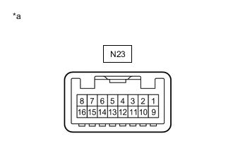
*a Component without harness connected
(Outer Rear View Mirror Assembly LH)
-
Remove the outer rear view mirror assembly LH.
-
Remove the side turn signal light assembly LH from the outer rear view mirror assembly LH.
-
Measure the resistance according to the value(s) in the table below.
Standard Resistance Tester Connection Condition Specified Condition N23-16 (B) - N23-12 (-) Always 10 kΩ or higher Result Proceed to OK NG
OK
REPLACE COMBINATION METER ASSEMBLY Click here
NG
REPLACE OUTER REAR VIEW MIRROR ASSEMBLY LH Click here
-
-
CHECK HARNESS AND CONNECTOR (REAR COMBINATION LIGHT ASSEMBLY RH - COMBINATION METER ASSEMBLY)
-
Disconnect the Q5 rear combination light assembly RH connector.
-
Disconnect the K4 combination meter assembly connector.
-
Measure the resistance according to the value(s) in the table below.
Standard Resistance Tester Connection Condition Specified Condition Q5-4 (TRN) or K4-5 (TRNR) - Body ground Always 10 kΩ or higher Result Proceed to OK NG
NG
REPAIR OR REPLACE HARNESS OR CONNECTOR
OK
-
-
CHECK HARNESS AND CONNECTOR (NO. 1 HEADLIGHT ECU SUB-ASSEMBLY RH - INSTRUMENT PANEL JUNCTION BLOCK ASSEMBLY)
-
Disconnect the G1 No. 1 headlight ECU sub-assembly RH connector.
-
Disconnect the 4C instrument panel junction block assembly connector.
-
Measure the resistance according to the value(s) in the table below.
Standard Resistance Tester Connection Condition Specified Condition G1-11 (TNS) or 4C-8 - Body ground Always 10 kΩ or higher Result Result Proceed to OK A NG B
B
REPAIR OR REPLACE HARNESS OR CONNECTOR
A
-
-
INSPECT INSTRUMENT PANEL JUNCTION BLOCK ASSEMBLY
*a Component without harness connected
(Instrument Panel Junction Block Assembly)
- -
-
Measure the resistance according to the value(s) in the table below.
Note
Make sure to perform this step with the instrument panel junction block assembly installed to the vehicle.
Standard Resistance Tester Connection Condition Specified Condition 4C-8 or 4A-5 - Body ground Always 10 kΩ or higher Result Proceed to OK NG
NG
REPLACE INSTRUMENT PANEL JUNCTION BLOCK ASSEMBLY Click here
OK
-
-
CONFIRM MODEL
Result Result Proceed to w/ Seat Position Memory A w/o Seat Position Memory B
B
CHECK HARNESS AND CONNECTOR (INSTRUMENT PANEL JUNCTION BLOCK ASSEMBLY AND OUTER REAR VIEW MIRROR ASSEMBLY RH - COMBINATION METER ASSEMBLY) Click here
A
-
CHECK HARNESS AND CONNECTOR (INSTRUMENT PANEL JUNCTION BLOCK ASSEMBLY AND OUTER MIRROR CONTROL ECU ASSEMBLY RH - COMBINATION METER ASSEMBLY)
-
Disconnect the 4A instrument panel junction block assembly connector.
-
Disconnect the N9 outer mirror control ECU assembly RH connector.
-
Measure the resistance according to the value(s) in the table below.
Standard Resistance Tester Connection Condition Specified Condition 4A-5, N9-11(TRNI) or K4-7 (LR) - Body ground Always 10 kΩ or higher Result Proceed to OK NG
NG
REPAIR OR REPLACE HARNESS OR CONNECTOR
OK
-
-
INSPECT OUTER REAR VIEW MIRROR ASSEMBLY RH

*a Component without harness connected
(Outer Rear View Mirror Assembly RH)
-
Remove the outer rear view mirror assembly RH.
-
Remove the side turn signal light assembly RH from the outer rear view mirror assembly RH.
-
Measure the resistance according to the value(s) in the table below.
Standard Resistance Tester Connection Condition Specified Condition z12-16 - z12-12 Always 10 kΩ or higher Result Proceed to OK NG
NG
REPLACE OUTER REAR VIEW MIRROR ASSEMBLY RH Click here
OK
-
-
REPLACE OUTER MIRROR CONTROL ECU ASSEMBLY RH
-
Replace the outer mirror control ECU assembly RH with a new or known good one.
-
Check for the DTCs.
Result Result Proceed to DTCs are not output A DTCs are output B
A
END
B
REPLACE COMBINATION METER ASSEMBLY Click here
-
-
CHECK HARNESS AND CONNECTOR (INSTRUMENT PANEL JUNCTION BLOCK ASSEMBLY AND OUTER REAR VIEW MIRROR ASSEMBLY RH - COMBINATION METER ASSEMBLY)
-
Disconnect the 4A instrument panel junction block assembly connector.
-
Disconnect the N8 outer rear view mirror assembly RH connector.
-
Measure the resistance according to the value(s) in the table below.
Standard Resistance Tester Connection Condition Specified Condition 4A-5, N8-16(B) or K4-7 (LR) - Body ground Always 10 kΩ or higher Result Proceed to OK NG
NG
REPAIR OR REPLACE HARNESS OR CONNECTOR
OK
-
-
INSPECT OUTER REAR VIEW MIRROR ASSEMBLY RH
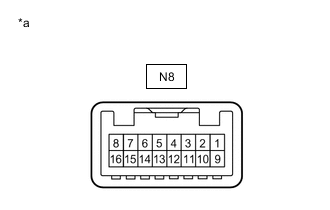
*a Component without harness connected
(Outer Rear View Mirror Assembly RH)
-
Remove the outer rear view mirror assembly RH.
-
Remove the side turn signal light assembly RH from the outer rear view mirror assembly RH.
-
Measure the resistance according to the value(s) in the table below.
Standard Resistance Tester Connection Condition Specified Condition N8-16 (B) - N8-12 (-) Always 10 kΩ or higher Result Proceed to OK NG
OK
REPLACE COMBINATION METER ASSEMBLY Click here
NG
REPLACE OUTER REAR VIEW MIRROR ASSEMBLY RH Click here
-