METER / GAUGE SYSTEM, Diagnostic DTC:B1500
| DTC Code | DTC Name |
|---|---|
| B1500 | Fuel Sender Open Detected |
DESCRIPTION
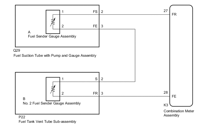
This DTC is stored when the combination meter assembly detects a fuel sender gauge assembly and No. 2 fuel sender gauge assembly malfunction via a direct line.
| DTC No. | Detection Item | DTC Detection Condition | Trouble Area | Memory | Note |
|---|---|---|---|---|---|
| B1500 | Fuel Sender Open Detected | When IG voltage is 9.5 V or more and the following condition is detected:
|
|
- | - |
WIRING DIAGRAM
PROCEDURE
-
READ VALUE USING GTS (FUEL INPUT)
-
Connect the GTS to the DLC3.
-
Turn the power switch on (IG).
-
Turn the GTS on.
-
Enter the following menus: Body Electrical / Combination Meter / Data List.
-
Check the values by referring to the table below.
Body Electrical > Combination Meter > Data ListTester Display Measurement Item Range Normal Condition Diagnostic Note Fuel Input Fuel input Min.: 0 L, Max. 127.5 L for F SPORT models:
Fuel receiver gauge indicates F: 64.8 L
Fuel receiver gauge indicates 3/4: 46.8 L
Fuel receiver gauge indicates 1/2: 35.1 L
Fuel receiver gauge indicates 1/4: 20.6 L
Fuel receiver gauge indicates E: 3.3 L
except F SPORT models:
Fuel receiver gauge indicates F: 64.8 L
Fuel receiver gauge indicates 3/4: 49.2 L
Fuel receiver gauge indicates 1/2: 30.8 L
Fuel receiver gauge indicates 1/4: 15.4 L
Fuel receiver gauge indicates E: 3.3 L
Unit: Liter
Body Electrical > Combination Meter > Data ListTester Display Fuel Input Result Result Proceed to Fuel level data can be displayed on the GTS and DTC B1500 is output. A Fuel level data cannot be displayed on the GTS. B
A 
REPLACE COMBINATION METER ASSEMBLY Click here
B 
-
-
INSPECT FUEL SENDER GAUGE ASSEMBLY
-
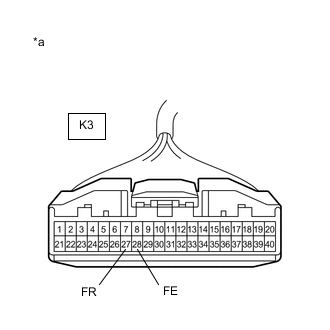
*a Front view of wire harness connector
(to Combination Meter Assembly)
Disconnect the K3 combination meter assembly connector.
-
Measure the resistance according to the value(s) in the table below.
Standard Resistance Tester Connection Condition Specified Condition K3-27 (FR) - K3-28 (FE) Always 13.0 to 415.5 Ω Result Proceed to OK NG
OK
REPLACE COMBINATION METER ASSEMBLY Click here
NG
-
-
CHECK HARNESS AND CONNECTOR (COMBINATION METER ASSEMBLY - FUEL SUCTION TUBE WITH PUMP AND GAUGE ASSEMBLY, FUEL TANK VENT TUBE SUB-ASSEMBLY)
-
Disconnect the Q29 fuel suction tube with pump and gauge assembly connector.
-
Disconnect the P22 fuel tank vent tube sub-assembly connector.
-
Measure the resistance according to the value(s) in the table below.
Standard Resistance Tester Connection Condition Specified Condition K3-27 (FR) - Q29-2 (FS) Always Below 1 Ω K3-28 (FE) - P22-3 (FR) Always Below 1 Ω Q29-3 (FE) - P22-2 (S) Always Below 1 Ω K3-27 (FR) - Body ground Always 10 kΩ or higher K3-28 (FE) - Body ground Always 10 kΩ or higher Q29-3 (FE) - Body ground Always 10 kΩ or higher Result Proceed to OK NG
NG
REPAIR OR REPLACE HARNESS OR CONNECTOR
OK
-
-
INSPECT FUEL SENDER GAUGE ASSEMBLY
-
Remove the fuel sender gauge assembly.
-
Inspect the fuel sender gauge assembly.
Result Proceed to OK NG
NG
REPLACE FUEL SENDER GAUGE ASSEMBLY Click here
OK
-
-
INSPECT FUEL SUCTION TUBE WITH PUMP AND GAUGE ASSEMBLY
-
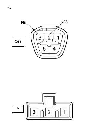
*a Component without harness connected
(Fuel Suction Tube with Pump and Gauge Assembly)
Measure the resistance according to the value(s) in the table below.
Standard Resistance Tester Connection Condition Specified Condition Q29-2 (FS) - A-1 Always Below 1 Ω Q29-3 (FE) - A-2 Always Below 1 Ω Result Proceed to OK NG
NG
REPLACE FUEL SUCTION TUBE WITH PUMP AND GAUGE ASSEMBLY Click here
OK
-
-
INSPECT NO. 2 FUEL SENDER GAUGE ASSEMBLY
-
Remove the No. 2 fuel sender gauge assembly.
-
Inspect the No. 2 fuel sender gauge assembly.
Result Proceed to OK NG
NG
REPLACE NO. 2 FUEL SENDER GAUGE ASSEMBLY Click here
OK
-
-
INSPECT FUEL TANK VENT TUBE SUB-ASSEMBLY
-
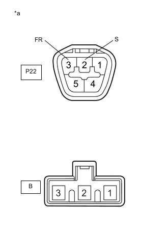
*a Component without harness connected
(Fuel Tank Vent Tube Sub-assembly)
Measure the resistance according to the value(s) in the table below.
Standard Resistance Tester Connection Condition Specified Condition P22-2 (S) - B-1 Always Below 1 Ω P22-3 (FR) - B-2 Always Below 1 Ω Result Proceed to OK NG
OK
REPLACE COMBINATION METER ASSEMBLY Click here
NG
REPLACE FUEL TANK VENT TUBE SUB-ASSEMBLY Click here
-