METER / GAUGE SYSTEM Odo/Trip Switch Malfunction
DESCRIPTION
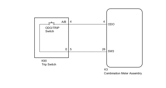
In this circuit, the combination meter assembly detects ODO/TRIP switch signals via a direct line.
WIRING DIAGRAM
PROCEDURE
-
READ VALUE USING GTS (ODO/TRIP CHANGE SW)
-
Connect the GTS to the DLC3.
-
Turn the power switch on (IG).
-
Turn the GTS on.
-
Enter the following menus: Body Electrical / Combination Meter / Data List.
-
Check the values by referring to the table below.
Body Electrical > Combination Meter > Data ListTester Display Measurement Item Range Normal Condition Diagnostic Note ODO/TRIP Change SW ODO/TRIP switch OFF or ON OFF: Switch released
ON: Switch pushed
-
Body Electrical > Combination Meter > Data ListTester Display ODO/TRIP Change SW OK ODO/TRIP switch condition displayed on the GTS changes with the actual switch operation. Result Proceed to OK NG
OK 
REPLACE COMBINATION METER ASSEMBLY Click here
NG 
-
-
INSPECT TRIP SWITCH
-
Remove the trip switch.
-
Inspect the trip switch.
Result Proceed to OK NG
NG
REPLACE TRIP SWITCH Click here
OK
-
-
CHECK HARNESS AND CONNECTOR (COMBINATION METER ASSEMBLY - TRIP SWITCH)
-
Disconnect the K3 combination meter assembly connector.
-
Measure the resistance according to the value(s) in the table below.
Standard Resistance Tester Connection Condition Specified Condition K3-4 (ODO) - K90-4 (A/B) Always Below 1 Ω K3-26 (SW3) - K90-5 (E) Always Below 1 Ω K3-4 (ODO) - Body ground Always 10 kΩ or higher K3-26 (SW3) - Body ground Always 10 kΩ or higher Result Proceed to OK NG
OK
REPLACE COMBINATION METER ASSEMBLY Click here
NG
REPAIR OR REPLACE HARNESS OR CONNECTOR
-