METER / GAUGE SYSTEM Engine Coolant Temperature Receiver Gauge Malfunction
DESCRIPTION
In this circuit, the combination meter assembly receives engine coolant temperature signals from the power management control ECU via the CAN communication system. The combination meter assembly displays the engine coolant temperature that is calculated based on the data received from the power management control ECU.
WIRING DIAGRAM
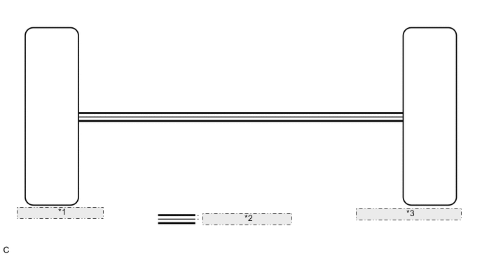
| *1 | Power Management Control ECU |
| *2 | CAN Communication Line |
| *3 | Combination Meter Assembly |
CAUTION / NOTICE / HINT
Tech Tips
-
If there is an open or short in the engine coolant temperature sensor circuit, the ECM stores DTCs. Troubleshoot the SFI system.
for 2AR-FSE (w/ EGR System): Click here
for 2AR-FSE (w/o EGR System): Click here
-
Active Test cannot be performed on the engine coolant temperature receiver gauge for F SPORT models.
PROCEDURE
-
CHECK CAN COMMUNICATION SYSTEM
-
Check if CAN communication DTCs are output.
Result Result Proceed to CAN communication DTCs are not output. A CAN communication DTCs are output. B
B 
GO TO CAN COMMUNICATION SYSTEM Click here
A 
-
-
CONFIRM MODEL
-
Confirm the vehicle type.
Result Result Proceed to except F SPORT models A for F SPORT models B
B 
GO TO STEP 4 Click here
A
-
-
PERFORM ACTIVE TEST USING GTS (WATER TEMPERATURE METER OPERATION)
-
Connect the GTS to the DLC3.
-
Turn the power switch on (IG).
-
Turn the GTS on.
-
Enter the following menus: Body Electrical / Combination Meter / Active Test.
-
Check the operation by referring to the table below.
Body Electrical > Combination Meter > Active TestTester Display Measurement Item Control Range Diagnostic Note Water Temperature Meter Operation Engine coolant temperature receiver gauge OFF, LOW, NORMAL, HIGH -
Body Electrical > Combination Meter > Active TestTester Display Water Temperature Meter Operation OK Engine coolant temperature receiver gauge indication is normal. Result Proceed to OK NG
NG
REPLACE COMBINATION METER ASSEMBLY Click here
OK
-
-
READ VALUE USING GTS (COOLANT TEMPERATURE)
-
Connect the GTS to the DLC3.
-
Turn the power switch on (IG).
-
Turn the GTS on.
-
Enter the following menus: Body Electrical / Combination Meter / Data List.
-
Check the values by referring to the table below.
Body Electrical > Combination Meter > Data ListTester Display Measurement Item Range Normal Condition Diagnostic Note Coolant Temperature Engine coolant temperature Min.: 0°C (0°F), Max.: 127.5°C (261.5°F) 75 to 100 °C (167 to 212°F): After warming up engine -
Body Electrical > Combination Meter > Data ListTester Display Coolant Temperature OK Engine coolant temperature displayed on the GTS is almost the same as the engine coolant temperature receiver gauge indication. Tech Tips
-
When the Data List values and engine coolant temperature receiver gauge values match, a signal output error of the ECM or an internal malfunction of the combination meter assembly is suspected.
-
When the Data List values and engine coolant temperature receiver gauge values do not match, an internal malfunction of the combination meter assembly is suspected.
Result Proceed to OK NG -
NG
REPLACE COMBINATION METER ASSEMBLY Click here
OK
-
-
CHECK FOR DTC
-
Check if hybrid control system DTCs are output.
Powertrain > Hybrid Control > Trouble CodesResult Result Proceed to Hybrid control system DTCs are not output. A Hybrid control system DTCs are output. B
B
GO TO HYBRID CONTROL SYSTEM Click here
A
-
-
READ VALUE USING GTS (COOLANT TEMP, COOLANT TEMPERATURE)
-
Connect the GTS to the DLC3.
-
Turn the power switch on (IG).
-
Turn the GTS on.
-
Enter the following menus:
-
for Hybrid: Powertrain / Hybrid Control / Data List.
-
for Combination Meter: Body Electrical / Combination Meter / Data List.
-
-
Check the values by referring to the table below.
-
Hybrid Control
Powertrain > Hybrid Control > Data ListTester Display Measurement Item Range Normal Condition Diagnostic Note Engine Coolant Temp Engine coolant temperature Min.: -40°C (-40°F), Max.: 215°C (419°F) Cold start→Fully warmed up:
Gradually rises
After warming up:
75 to 100°C (167 to 212°F)
-
Powertrain > Hybrid Control > Data ListTester Display Engine Coolant Temp -
Combination Meter
Body Electrical > Combination Meter > Data ListTester Display Measurement Item Range Normal Condition Diagnostic Note Coolant Temperature Engine coolant temperature Min.: 0°C (0°F), Max.: 127.5°C (261.5°F) 75 to 100 °C (167 to 212°F): After warming up engine -
Body Electrical > Combination Meter > Data ListTester Display Coolant Temperature
Result Result Proceed to Data List values of the ECUs match. A Data List values of the ECUs do not match. B Tech Tips
-
When the Data List values of the ECUs match, an internal malfunction of the ECM is suspected.
-
When the Data List values of the ECUs do not match, a signal output error of the ECM or an internal malfunction of the combination meter assembly is suspected.
-
B
REPLACE POWER MANAGEMENT CONTROL ECU Click here
A
-
-
REPLACE COMBINATION METER ASSEMBLY
-
Replace the combination meter assembly with a new or known good one.
OK The operation of the engine coolant temperature receiver gauge returns to normal. Result Proceed to OK NG
OK
END
NG
REPLACE POWER MANAGEMENT CONTROL ECU Click here
-