LIGHTING SYSTEM Door Unlock Detection Switch Circuit
DESCRIPTION
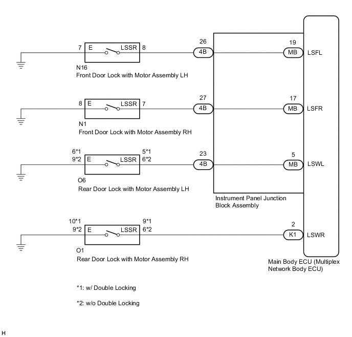
The main body ECU (multiplex network body ECU) detects the condition of each door unlock detection switch.
WIRING DIAGRAM
CAUTION / NOTICE / HINT
Note
Before replacing the main body ECU (multiplex network body ECU), refer to Service Bulletin.
PROCEDURE
-
READ VALUE USING GTS
-
Connect the GTS to the DLC3.
-
Turn the power switch on (IG).
-
Turn the GTS on.
-
Enter the following menus: Body Electrical / Main Body / Data List.
-
Read the Data List according to the display on the GTS.
Body Electrical > Main Body > Data ListTester Display Measurement Item Range Normal Condition Diagnostic Note FR Door Lock Pos Front door RH unlock detection switch signal LOCK or UNLOCK LOCK: Front door RH locked
UNLOCK: Front door RH unlocked
- FL Door Lock Pos Front door LH unlock detection switch signal LOCK or UNLOCK LOCK: Front door LH locked
UNLOCK: Front door LH unlocked
- RR-Door Lock Pos SW Rear door RH unlock detection switch signal ON or OFF ON: Rear door RH unlocked
OFF: Rear door RH locked
- RL-Door Lock Pos SW Rear door LH unlock detection switch signal ON or OFF ON: Rear door LH unlocked
OFF: Rear door LH locked
-
Body Electrical > Main Body > Data ListTester Display FR Door Lock Pos FL Door Lock Pos RR-Door Lock Pos SW RL-Door Lock Pos SW Result Result Proceed to OK A FL Door Lock Pos is not normal B FR Door Lock Pos is not normal C RL-Door Lock Pos SW is not normal D RR-Door Lock Pos SW is not normal E
A 
PROCEED TO NEXT SUSPECTED AREA SHOWN IN PROBLEM SYMPTOMS TABLE Click here
C 
INSPECT FRONT DOOR LOCK WITH MOTOR ASSEMBLY RH Click here
D
INSPECT REAR DOOR LOCK WITH MOTOR ASSEMBLY LH Click here
E
INSPECT REAR DOOR LOCK WITH MOTOR ASSEMBLY RH Click here
B 
-
-
INSPECT FRONT DOOR LOCK WITH MOTOR ASSEMBLY LH
-
Remove the front door lock with motor assembly LH.
-
Inspect the front door lock with motor assembly LH.
OK Front door lock with motor assembly LH is normal. Result Proceed to OK NG
NG
REPLACE FRONT DOOR LOCK WITH MOTOR ASSEMBLY LH Click here
OK
-
-
CHECK HARNESS AND CONNECTOR (FRONT DOOR LOCK WITH MOTOR ASSEMBLY LH - INSTRUMENT PANEL JUNCTION BLOCK ASSEMBLY OR BODY GROUND)
-
Disconnect the 4B instrument panel junction block assembly connector.
-
Measure the resistance according to the value(s) in the table below.
Standard Resistance Tester Connection Condition Specified Condition N16-8 (LSSR) - 4B-26 Always Below 1 Ω N16-8 (LSSR) - Body ground Always 10 kΩ or higher N16-7 (E) - Body ground Always Below 1 Ω Result Proceed to OK NG
NG
REPAIR OR REPLACE HARNESS OR CONNECTOR
OK
-
-
INSPECT INSTRUMENT PANEL JUNCTION BLOCK ASSEMBLY
-
Remove the instrument panel junction block assembly.
-
Remove the main body ECU (multiplex network body ECU) from the instrument panel junction block assembly.
-
Measure the resistance according to the value(s) in the table below.
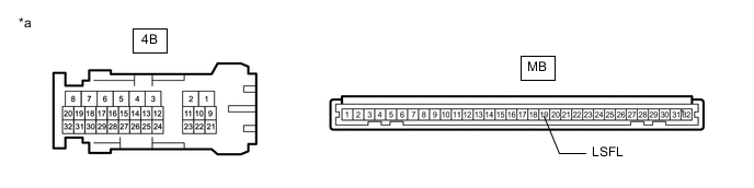
*a Component without harness connected
(Instrument Panel Junction Block Assembly)
- - Standard Resistance Tester Connection Condition Specified Condition MB-19 (LSFL) - 4B-26 Always Below 1 Ω Result Proceed to OK NG
OK
REPLACE MAIN BODY ECU (MULTIPLEX NETWORK BODY ECU) Click here
NG
REPLACE INSTRUMENT PANEL JUNCTION BLOCK ASSEMBLY Click here
-
-
INSPECT FRONT DOOR LOCK WITH MOTOR ASSEMBLY RH
-
Remove the front door lock with motor assembly RH.
-
Inspect the front door lock with motor assembly RH.
OK Front door lock with motor assembly RH is normal. Result Proceed to OK NG
NG
REPLACE FRONT DOOR LOCK WITH MOTOR ASSEMBLY RH Click here
OK
-
-
CHECK HARNESS AND CONNECTOR (FRONT DOOR LOCK WITH MOTOR ASSEMBLY RH - INSTRUMENT PANEL JUNCTION BLOCK ASSEMBLY OR BODY GROUND)
-
Disconnect the 4B instrument panel junction block assembly connector.
-
Measure the resistance according to the value(s) in the table below.
Standard Resistance Tester Connection Condition Specified Condition N1-7 (LSSR) - 4B-27 Always Below 1 Ω N1-7 (LSSR) - Body ground Always 10 kΩ or higher N1-8 (E) - Body ground Always Below 1 Ω Result Proceed to OK NG
NG
REPAIR OR REPLACE HARNESS OR CONNECTOR
OK
-
-
INSPECT INSTRUMENT PANEL JUNCTION BLOCK ASSEMBLY
-
Remove the instrument panel junction block assembly.
-
Remove the main body ECU (multiplex network body ECU) from the instrument panel junction block assembly.
-
Measure the resistance according to the value(s) in the table below.
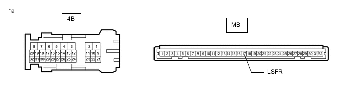
*a Component without harness connected
(Instrument Panel Junction Block Assembly)
- - Standard Resistance Tester Connection Condition Specified Condition MB-17 (LSFR) - 4B-27 Always Below 1 Ω Result Proceed to OK NG
OK
REPLACE MAIN BODY ECU (MULTIPLEX NETWORK BODY ECU) Click here
NG
REPLACE INSTRUMENT PANEL JUNCTION BLOCK ASSEMBLY Click here
-
-
INSPECT REAR DOOR LOCK WITH MOTOR ASSEMBLY LH
-
Remove the rear door lock with motor assembly LH.
-
Inspect the rear door lock with motor assembly LH.
OK Rear door lock with motor assembly LH is normal. Result Proceed to OK NG
NG
REPLACE REAR DOOR LOCK WITH MOTOR ASSEMBLY LH Click here
OK
-
-
CHECK HARNESS AND CONNECTOR (REAR DOOR LOCK WITH MOTOR ASSEMBLY LH - INSTRUMENT PANEL JUNCTION BLOCK ASSEMBLY OR BODY GROUND)
-
Disconnect the 4B instrument panel junction block assembly connector.
-
Measure the resistance according to the value(s) in the table below.
Standard Resistance w/ Double Locking Tester Connection Condition Specified Condition O6-5 (LSSR) - 4B-23 Always Below 1 Ω O6-5 (LSSR) - Body ground Always 10 kΩ or higher O6-6 (E) - Body ground Always Below 1 Ω Standard Resistance w/o Double Locking Tester Connection Condition Specified Condition O6-6 (LSSR) - 4B-23 Always Below 1 Ω O6-6 (LSSR) - Body ground Always 10 kΩ or higher O6-9 (E) - Body ground Always Below 1 Ω Result Proceed to OK NG
NG
REPAIR OR REPLACE HARNESS OR CONNECTOR
OK
-
-
INSPECT INSTRUMENT PANEL JUNCTION BLOCK ASSEMBLY
-
Remove the instrument panel junction block assembly.
-
Remove the main body ECU (multiplex network body ECU) from the instrument panel junction block assembly.
-
Measure the resistance according to the value(s) in the table below.
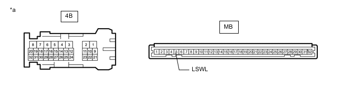
*a Component without harness connected
(Instrument Panel Junction Block Assembly)
- - Standard Resistance Tester Connection Condition Specified Condition MB-5 (LSWL) - 4B-23 Always Below 1 Ω Result Proceed to OK NG
OK
REPLACE MAIN BODY ECU (MULTIPLEX NETWORK BODY ECU) Click here
NG
REPLACE INSTRUMENT PANEL JUNCTION BLOCK ASSEMBLY Click here
-
-
INSPECT REAR DOOR LOCK WITH MOTOR ASSEMBLY RH
-
Remove the rear door lock with motor assembly RH.
-
Inspect the rear door lock with motor assembly RH.
OK Rear door lock with motor assembly RH is normal. Result Proceed to OK NG
NG
REPLACE REAR DOOR LOCK WITH MOTOR ASSEMBLY RH Click here
OK
-
-
CHECK HARNESS AND CONNECTOR (REAR DOOR LOCK WITH MOTOR ASSEMBLY RH - MAIN BODY ECU (MULTIPLEX NETWORK BODY ECU) OR BODY GROUND)
-
Disconnect the K1 main body ECU (multiplex network body ECU) connector.
-
Measure the resistance according to the value(s) in the table below.
Standard Resistance w/ Double Locking Tester Connection Condition Specified Condition O1-9 (LSSR) - K1-2 (LSWR) Always Below 1 Ω O1-9 (LSSR) - Body ground Always 10 kΩ or higher O1-10 (E) - Body ground Always Below 1 Ω Standard Resistance w/o Double Locking Tester Connection Condition Specified Condition O1-6 (LSSR) - K1-2 (LSWR) Always Below 1 Ω O1-6 (LSSR) - Body ground Always 10 kΩ or higher O1-9 (E) - Body ground Always Below 1 Ω Result Proceed to OK NG
OK
REPLACE MAIN BODY ECU (MULTIPLEX NETWORK BODY ECU) Click here
NG
REPAIR OR REPLACE HARNESS OR CONNECTOR
-