| DTC Code | DTC Name |
|---|---|
| Interior Light Circuit |
DESCRIPTION
The main body ECU (multiplex network body ECU) controls the operation of the following lights:
-
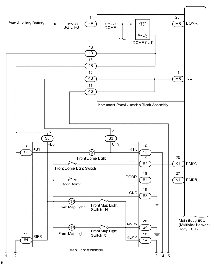
Map Light Assembly (Front Dome Light)
-
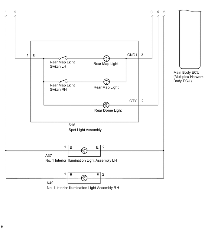
Spot Light Assembly (Rear Dome Light)
-
No. 1 Interior Illumination Light Assembly LH
-
No. 1 Interior Illumination Light Assembly RH
CAUTION / NOTICE / HINT
-
Inspect the fuses and lights for circuits related to this system before performing the following procedure.
-
Before replacing the main body ECU (multiplex network body ECU), refer to Service Bulletin.
The DOME CUT relay supplies power to the interior lights. If all the lights that use power from the DOME CUT relay do not turn on, check the interior light auto cut circuit first.
PROCEDURE
- Click here
PERFORM ACTIVE TEST USING GTS
-
Connect the GTS to the DLC3.
-
Turn the power switch on (IG).
-
Turn the GTS on.
-
Enter the following menus: Body Electrical / Main Body / Active Test.
-
Perform the Active Test according to the display on the GTS.
- Body Electrical > Main Body > Active Test
Tester Display Measurement Item Control Range Diagnostic Note Illuminated Entry System Turns on the lights that are controlled by the illuminated entry system*1 ON or OFF Perform the Active Test with door switch in the map light assembly turned on. -
-
-
*1: Refer to Description for the lights that are controlled by the illuminated entry system.
- Body Electrical > Main Body > Active Test
Tester Display Illuminated Entry System -
-
-
-
Result Proceed to OK NG - Body Electrical > Main Body > Active Test
- OK
PROCEED TO NEXT SUSPECTED AREA SHOWN IN PROBLEM SYMPTOMS TABLEClick here
- NGClick here
-
- Click here
INSPECT INSTRUMENT PANEL JUNCTION BLOCK ASSEMBLY
-
Remove the instrument panel junction block assembly.
-
Remove the main body ECU (multiplex network body ECU) from the instrument panel junction block assembly.
-
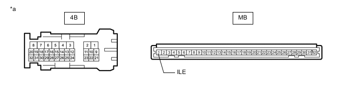
*a Component without harness connected
(Instrument Panel Junction Block Assembly)
- - Measure the resistance according to the value(s) in the table below.
Standard Resistance Tester Connection Condition Specified Condition 4B-10 - MB-1 (ILE) Always Below 1 Ω 4B-11 - MB-1 (ILE) Always Below 1 Ω Result Proceed to OK NG
- OK
REPLACE MAIN BODY ECU (MULTIPLEX NETWORK BODY ECU)Click here
- NG
REPLACE INSTRUMENT PANEL JUNCTION BLOCK ASSEMBLYClick here
-