THEFT DETERRENT SYSTEM Theft Warning Siren Circuit
DESCRIPTION
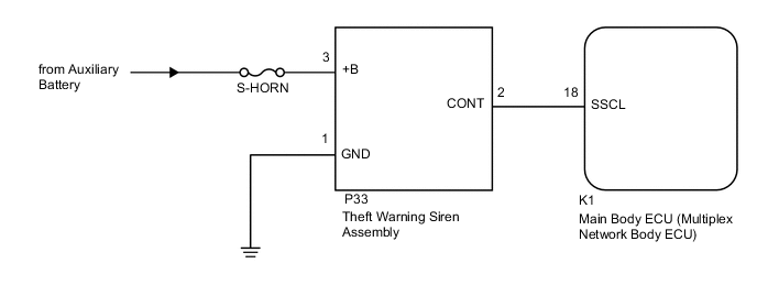
The theft warning siren assembly sounds if either of the following conditions is met:
-
The theft deterrent system is in the alarm sounding state.
-
The theft warning siren assembly is in the armed state when the power source, ground or communication line is open.
WIRING DIAGRAM
CAUTION / NOTICE / HINT
Note
-
If the main body ECU (multiplex network body ECU) is replaced, refer to Service Bulletin.
-
Inspect the fuses for circuits related to this system before performing the following procedure.
PROCEDURE
-
PERFORM ACTIVE TEST USING GTS (SECURITY HORN2)
-
Connect the GTS to the DLC3.
-
Turn the power switch on (IG).
-
Turn the GTS on.
-
Enter the following menus: Body Electrical / Main Body / Active Test.
-
Perform the Active Test according to the display on the GTS.
Body Electrical > Main Body > Active TestTester Display Measurement Item Control Range Diagnostic Note Security Horn2 Theft warning siren assembly OFF/ON -
Body Electrical > Main Body > Active TestTester Display Security Horn2 OK The theft warning siren assembly sounds and stops correctly when operated using the GTS. Result Proceed to OK NG
OK 
REPLACE MAIN BODY ECU (MULTIPLEX NETWORK BODY ECU) Click here
NG 
-
-
CHECK HARNESS AND CONNECTOR (AUXILIARY BATTERY - THEFT WARNING SIREN ASSEMBLY - BODY GROUND)
-
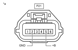
*a Front view of wire harness connector
(to Theft Warning Siren Assembly)
Disconnect the P21 theft warning siren assembly connector.
-
Measure the voltage and resistance according to the value(s) in the table below.
Standard Voltage Tester Connection Condition Specified Condition P21-5 (+B) - Body ground Power switch off 11 to 14 V Standard Resistance Tester Connection Condition Specified Condition P21-2 (GND) - Body ground Always Below 1 Ω Result Proceed to OK NG
NG
REPAIR OR REPLACE HARNESS OR CONNECTOR
OK
-
-
CHECK HARNESS AND CONNECTOR (MAIN BODY ECU (MULTIPLEX NETWORK BODY ECU) - THEFT WARNING SIREN ASSEMBLY)
-
Disconnect the K1 main body ECU (multiplex network body ECU) connector.
-
Measure the resistance according to the value(s) in the table below.
Standard Resistance Tester Connection Condition Specified Condition K1-18 (SSCL) - P21-4 (CONT) Always Below 1 Ω K1-18 (SSCL) - Body ground Always 10 kΩ or higher P21-4 (CONT) - Body ground Always 10 kΩ or higher Result Proceed to OK NG
NG
REPAIR OR REPLACE HARNESS OR CONNECTOR
OK
-
-
REPLACE THEFT WARNING SIREN ASSEMBLY
-
Temporarily replace the theft warning siren assembly with a new or known good one.
Tech Tips
Refer to Service Bulletin.
Result Proceed to NEXT
NEXT
-
-
CHECK THEFT WARNING SIREN ASSEMBLY
-
Turn the power switch on (IG), then off.
-
Set the theft deterrent system to "ARMED STATE".
-
Check that the security indicator changes from illuminated to blinking.
-
Change the theft deterrent system to "ALARM SOUNDING STATE".
-
Check that the theft warning siren assembly is sounding.
OK Theft warning siren assembly is sounding. Result Proceed to OK NG
OK
END (THEFT WARNING SIREN ASSEMBLY WAS DEFECTIVE)
NG
REPLACE MAIN BODY ECU (MULTIPLEX NETWORK BODY ECU) Click here
-