ENTRY AND START SYSTEM(for Start Function) TERMINALS OF ECU
-
CHECK POWER MANAGEMENT CONTROL ECU
-
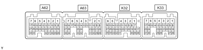
Disconnect the K32 and K33 power management control ECU connectors.
-
Measure the voltage and resistance according to the value(s) in the table below.
Tech Tips
Measure the values on the wire harness side with the connector disconnected.
Tester Connection Input/Output Wiring Color Terminal Description Condition Specified Condition Related Data List Item K33-10 (STP) - Body ground Input R - Body ground Stop light switch signal Brake pedal depressed → Brake pedal released 9 V or higher → 1 V or less Stop Light Switch1 K33-7 (AM21) -K32-6 (E1) Input BE - BR Power source Power switch off 11 to 14 V - K32-1 (AM22) -K32-6 (E1) Input BE - BR Power source Power switch off 11 to 14 V - K33-12 (SLP) - K32-6 (E1) Input R - BR Steering lock position signal Steering locked 10 kΩ or higher Steering Unlock Switch K33-14 (P2) - K32-6 (E1) Input LG - BR P position signal Shift lever in P → Shift lever not in P 30 kΩ or higher → Below 200 Ω Shift P Signal K32-5 (E01) - Body ground - W-B - Body ground Ground Always Below 1 Ω - K33-5 (E02) - Body ground - W-B - Body ground Ground Always Below 1 Ω - K32-6 (E1) - Body ground - BR - Body ground Ground Always Below 1 Ω - K33-4 (E12) - Body ground - W-B - Body ground Ground Always Below 1 Ω - K33-17 (SSW2) - Body ground Input L - Body ground SSW2 contact signal
Tech Tips
Backup for SSW1. Behaves the same way as SSW1.
Power switch pushed → Power switch not pushed Below 15 Ω → 10 kΩ or higher Start Switch2 K32-7 (SSW1) - Body ground Input GR - Body ground SSW1 contact signal Power switch pushed → Power switch not pushed Below 15 Ω → 10 kΩ or higher Start Switch1 K33-1 (ACCD) - Body ground Output P - Body ground ACC signal 20°C (68°F) 130.92 to 190.74 Ω ACC Relay Monitor K33-2 (IG1D) - Body ground Output V - Body ground IG signal 20°C (68°F) 87.32 to 127.14 Ω IG Relay Monitor (Outside) K32-16 (SPDI) - Body ground Input L - Body ground Vehicle speed signal Always 30 kΩ or higher Vehicle Speed Signal -
Reconnect the K32 and K33 power management control ECU connectors.
-
Measure the voltage and check for pulses according to the value(s) in the table below.
Tester Connection Input/Output Wiring Color Terminal Description Condition Specified Condition Related Data List Item K33-10 (STP) - K32-6 (E1) Input R - BR Stop light switch signal Brake pedal depressed → Brake pedal released 9 V or higher → 1 V or less Stop Light Switch1 K33-12 (SLP) - K32-6 (E1) Input R - BR Steering lock position signal Steering locked → Steering unlocked 11 to 14 V → 1.5 V or less Steering Unlock Switch K33-6 (SLR+) - K32-6 (E1) Output W - BR Steering lock motor operation command signal
(Steering lock motor operation permission signal sent from the power management control ECU)
When a door is opened, the steering lock motor will be operated if all of the following conditions are met:
-
The steering is unlocked.
-
The power switch is off.
-
The shift lever is in P.
Pulse generation
(See waveform 1)
- K33-14 (P2) - K32-6 (E1) Input LG - BR P position signal Shift lever in P → Shift lever not in P 9 V or higher → 2.76 V or less Shift P Signal K33-17 (SSW2) - K32-6 (E1) Input L - BR SSW2 contact signal
Tech Tips
Backup for SSW1. Behaves the same way as SSW1.
Power switch not pushed → Power switch pushed 9 V or higher → 1 V or less Start Switch2 K32-7 (SSW1) -K32-6 (E1) Input GR - BR SSW1 contact signal Power switch not pushed → Power switch pushed 9 V or higher → 1 V or less Start Switch1 K33-1 (ACCD) - K32-6 (E1) Output P - BR ACC signal Power switch off → Power switch on (ACC) 1 V or less → 8.5 V or higher ACC Relay Monitor K33-2 (IG1D) - K32-6 (E1) Output V - BR IG signal Power switch on (ACC) → Power switch on (IG) 1 V or less → 9 V or higher IG Relay Monitor (Outside) K32-16 (SPDI) - K32-6 (E1) Input L - BR Vehicle speed signal Vehicle being driven at approx. 5 km/h (3 mph) Pulse generation
(See waveform 2)
Vehicle Speed Signal Tech Tips
-
The waveform of the steering lock actuator motor stopped can be checked without performing any particular operation.
-
The waveform of the steering lock actuator motor operating can be checked if either of the following operations is performed:
-
To unlock the steering, bring the electrical key transmitter sub-assembly into the cabin and turn the power switch on (ACC) or on (IG).
-
To lock the steering, open a door with the power switch off and the shift lever in P.
-
-
Using an oscilloscope, check the waveform of the ECU.
Note
The oscilloscope waveform shown in the illustration is an example for reference only. Noise, chattering, etc. are not shown.
-
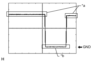
*a Steering lock motor not operating *b Steering lock motor operating Waveform 1
Item Content Tester Connection K33-6 (SLR+) - K32-6 (E1) Tool Setting 2 V/DIV., 200 ms./DIV. Condition Steering lock motor stopped → Steering lock motor operating → Steering lock motor stopped -
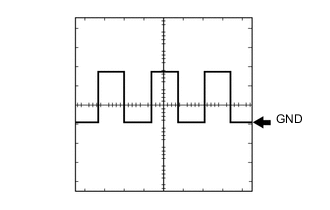
Waveform 2
Item Content Tester Connection K32-16 (SPDI) - K32-6 (E1) Tool Setting 5 V/DIV., 20 ms./DIV. Condition Vehicle being driven at approx. 5 km/h (3 mph) Tech Tips
The wavelength becomes shorter as the vehicle speed increases.
-
-
-
CHECK STEERING LOCK ECU (STEERING LOCK ACTUATOR ASSEMBLY)
-
CHECK ID CODE BOX (IMMOBILISER CODE ECU)
-
CHECK POWER SWITCH