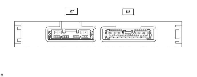
ENTRY AND START SYSTEM(for Entry Function) TERMINALS OF ECU
-
CHECK CERTIFICATION ECU (SMART KEY ECU ASSEMBLY)
-
Disconnect the K8 certification ECU (smart key ECU assembly) connector.
-
Measure the voltage and resistance according to the value(s) in the table below.
Tester Connection Input/Output Wiring Color Terminal Description Condition Specified Condition Related Data List Item K8-1 (E) - Body ground - BR - Body ground Ground Always Below 1 Ω - K8-10 (+B) - K8-1 (E) Input G - BR Power supply Power switch off 11 to 14 V - -
Reconnect the K8 certification ECU (smart key ECU assembly) connector.
-
Measure the voltage and check for pulses according to the value(s) in the table below.
Tester Connection Input/Output Wiring Color Terminal Description Condition Specified Condition Related Data List Item K8-4 (CLG1) - K8-1 (E) Output G*1 - BR
GR*2 - BR
Output to driver door electrical key antenna
(request signal (challenge) is sent to door electrical key antenna from certification ECU (smart key ECU assembly) to form detection area)
Procedure:
-
Power switch off
-
All doors closed
-
Electrical key transmitter sub-assembly not inside vehicle
-
All doors locked through wireless operation
(electrical key transmitter sub-assembly brought inside detection area*3)
Pulse generation
(See waveform 1)
Overhead + Driver Side (key diagnostic mode) Procedure:
-
Power switch off
-
All doors closed
-
Electrical key transmitter sub-assembly not inside vehicle
-
All doors locked through wireless operation
(electrical key transmitter sub-assembly brought outside detection area*3)
Pulse generation
(See waveform 2)
K8-4 (CLG1) - K8-1 (E) Input G*1 - BR
GR*2 - BR
Input to driver door lock sensor
(front door outside handle assembly (for driver side) lock sensor on signal is sent to the certification ECU (smart key ECU assembly))
Procedure:
-
Power switch off
-
Electrical key transmitter sub-assembly brought outside vehicle
-
All doors closed
-
All doors locked through wireless operation
(electrical key transmitter sub-assembly brought outside detection area*3)
-
Driver door lock sensor touched
Pulse generation
(See waveform 9)
D-Door Trigger Switch K8-4 (CLG1) - K8-1 (E) Input G*1 - BR
GR*2 - BR
Input to driver door unlock sensor
(when system is in unlock standby mode and unlock sensor is touched, door electrical key antenna sends unlock sensor input signal (sensing) to certification ECU (smart key ECU assembly))
Procedure:
-
Power switch off
-
Electrical key transmitter sub-assembly brought outside vehicle
-
All doors locked
-
Electrical key transmitter sub-assembly not near the vehicle
-
Driver door unlock sensor touched
Pulse generation
(See waveform 10)
D-Door Touch Sensor K8-3 (CG1B) - K8-1 (E) Output B*1 - BR
R*2 - BR
Output to driver door electrical key antenna (terminal on opposite side of component from CLG1 output terminal) Procedure:
-
Power switch off
-
All doors closed
-
Electrical key transmitter sub-assembly not inside vehicle
-
All doors locked through wireless operation
(electrical key transmitter sub-assembly brought inside detection area*3)
Pulse generation
(See waveform 1)
Overhead + Driver Side (key diagnostic mode) Procedure:
-
Power switch off
-
All doors closed
-
Electrical key transmitter sub-assembly not inside vehicle
-
All doors locked through wireless operation
(electrical key transmitter sub-assembly brought outside detection area*3)
Pulse generation
(See waveform 2)
K8-12 (CLG2) - K8-1 (E) Output GR*1 - BR
G*2 - BR
Output to front passenger door electrical key antenna
(request signal (challenge) is sent to door electrical key antenna from certification ECU (smart key ECU assembly) to form detection area)
Procedure:
-
Power switch off
-
All doors closed
-
Electrical key transmitter sub-assembly not inside vehicle
-
All doors locked through wireless operation
(electrical key transmitter sub-assembly brought inside detection area*3)
Pulse generation
(See waveform 1)
Overhead + Passenger Side (key diagnostic mode) Procedure:
-
Power switch off
-
All doors closed
-
Electrical key transmitter sub-assembly not inside vehicle
-
All doors locked through wireless operation
(electrical key transmitter sub-assembly brought outside detection area*3)
Pulse generation
(See waveform 2)
K8-12 (CLG2) - K8-1 (E) Input GR*1 - BR
G*2 - BR
Input to front passenger door lock sensor
(front door outside handle assembly (for front passenger door) lock sensor on signal is sent to the certification ECU (smart key ECU assembly))
Procedure:
-
Power switch off
-
Electrical key transmitter sub-assembly brought outside vehicle
-
All doors closed
-
All doors locked through wireless operation
(electrical key transmitter sub-assembly brought outside detection area*3)
-
Front passenger door lock sensor touched
Pulse generation
(See waveform 9)
P-Door Trigger Switch K8-12 (CLG2) - K8-1 (E) Input GR*1 - BR
G*2 - BR
Input to front passenger door unlock sensor
(when system is in unlock standby mode and unlock sensor is touched, door electrical key antenna sends unlock sensor input signal (sensing) to certification ECU (smart key ECU assembly))
Procedure:
-
Power switch off
-
Electrical key transmitter sub-assembly brought outside vehicle
-
All doors locked
-
Electrical key transmitter sub-assembly not near the vehicle
-
Front passenger door unlock sensor touched
Pulse generation
(See waveform 10)
P-Door Touch Sensor K8-11 (CG2B) - K8-1 (E) Output R*1 - BR
B*2 - BR
Output to front passenger door electrical key antenna (terminal on opposite side of component from CLG2 output terminal) Procedure:
-
Power switch off
-
All doors closed
-
Electrical key transmitter sub-assembly not inside vehicle
-
All doors locked through wireless operation
(electrical key transmitter sub-assembly brought inside detection area*3)
Pulse generation
(See waveform 1)
Overhead + Passenger Side (key diagnostic mode) Procedure:
-
Power switch off
-
All doors closed
-
Electrical key transmitter sub-assembly not inside vehicle
-
All doors locked through wireless operation
(electrical key transmitter sub-assembly brought outside detection area*3)
Pulse generation
(See waveform 2)
K8-8 (CLG5) - K8-1 (E) Output B - BR Output to No. 2 indoor electrical key antenna assembly (front floor) Procedure:
-
Power switch off
-
Electrical key transmitter sub-assembly not inside vehicle
-
Within 30 seconds of closing any door using the door outside handle
Pulse generation
(See waveform 3)
Overhead + Front Room (key diagnostic mode) K8-7 (CG5B) - K8-1 (E) Output V - BR Output to No. 2 indoor electrical key antenna assembly (front floor) (terminal on opposite side of component from CLG5 output terminal) Procedure:
-
Power switch off
-
Electrical key transmitter sub-assembly not inside vehicle
-
Within 30 seconds of closing any door using the door outside handle
Pulse generation
(See waveform 3)
Overhead + Front Room (key diagnostic mode) K8-5 (TSW5) - K8-1 (E) Input G - BR Luggage electrical key switch signal input Luggage electrical key switch off → on Pulse generation
(See waveform 6)
Tr/B-Door Unlock SW K7-10 (CLG6) - K8-1 (E) Output LG - BR Output to indoor electrical key antenna (rear floor) Procedure:
-
Power switch off
-
Electrical key transmitter sub-assembly not inside vehicle
-
Within 30 seconds of closing any door using the door outside handle
Pulse generation
(See waveform 3)
Overhead + Rear Room (key diagnostic mode) K7-9 (CG6B) - K8-1 (E) Output BE - BR Output to indoor electrical key antenna (rear floor) (terminal on opposite side of component from CLG6 output terminal) Procedure:
-
Power switch off
-
Electrical key transmitter sub-assembly not inside vehicle
-
Within 30 seconds of closing any door using the door outside handle
Pulse generation
(See waveform 3)
Overhead + Rear Room (key diagnostic mode) K7-8 (CLG7) - K8-1 (E) Output SB - BR Output to No. 1 indoor electrical key antenna assembly (inside luggage) Procedure:
-
Door is closed
-
Power switch off
-
Electrical key transmitter sub-assembly not inside vehicle
-
Driver door lock sensor touched
Pulse generation
(See waveform 4)
Luggage + Luggage (inside) (key diagnostic mode) K7-7 (CG7B) - K8-1 (E) Output P - BR Output to No. 1 indoor electrical key antenna assembly (inside luggage) (terminal on opposite side of component from CLG7 output terminal) Procedure:
-
Door is closed
-
Power switch off
-
Electrical key transmitter sub-assembly not inside vehicle
-
Driver door lock sensor touched
Pulse generation
(See waveform 4)
Luggage + Luggage (inside) (key diagnostic mode) K7-1 (RCO) - K8-1 (E) Output LG - BR Output to door control receiver
(Power supply for door control receiver. Certification ECU (smart key ECU assembly) outputs 5 V when receiver starts operating.)
Procedure:
-
Power switch off
-
Electrical key transmitter sub-assembly brought outside detection area but kept inside wireless function operational area
-
Lock or unlock switch of electrical key transmitter sub-assembly not pressed → pressed
Pulse generation
(See waveform 7)
- K7-2 (CSEL) - K8-1 (E) Output B - BR Communication channel switching circuit Procedure:
-
Power switch off
-
All doors closed
Below 1 V → pulse generation - K7-3 (RDAM) - K8-1 (E) Input R - BR Door control receiver verifies data received from electrical key transmitter sub-assembly.
Door control receiver sends data from electrical key transmitter sub-assembly to certification ECU (smart key ECU assembly) (Door control receiver intermittently grounds 12 V signal from certification ECU (smart key ECU assembly)).
Proceed:
-
Power switch off
-
All doors locked
-
Electrical key transmitter sub-assembly not inside vehicle
-
Electrical key transmitter sub-assembly brought outside detection area but kept inside wireless function operational area
-
Lock or unlock switch of electrical key transmitter sub-assembly not pressed → pressed
Pulse generation
(See waveform 8)
- K7-6 (CLG8) - K8-1 (E) Output B - BR Output to electrical key antenna (outside luggage compartment) Procedure:
-
Power switch off
-
Electrical key transmitter sub-assembly brought outside vehicle
-
All doors closed
-
Luggage electrical key switch off → on
Pulse generation
(See waveform 5)
Overhead + Luggage (key diagnostic mode) K7-5 (CG8B) - K8-1 (E) Output W - BR Output to electrical key antenna (outside luggage compartment) (terminal on opposite side of component from CLG8 output terminal) Procedure:
-
Power switch off
-
Electrical key transmitter sub-assembly brought outside vehicle
-
All doors closed
-
Luggage electrical key switch off → on
Pulse generation
(See waveform 5)
Overhead + Luggage (key diagnostic mode)
-
*1: for LHD
-
*2: for RHD
-
*3: For details about the entry function detection area, refer to Operation Check.
-
-
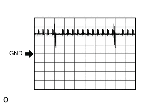
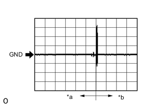
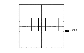
Using an oscilloscope, check waveform 1.
Note
The oscilloscope waveform shown in the illustration is an example for reference only. Noise, chattering, etc. are not shown.
Waveform 1 (Reference) Item Content Tester Connection K8-4 (CLG1) - K8-1 (E)
K8-3 (CG1B) - K8-1 (E)
K8-12 (CLG2) - K8-1 (E)
K8-11 (CG2B) - K8-1 (E)
Tool Setting 5 V/DIV., 500 ms/DIV. Condition Procedure:
-
Power switch off
-
All doors closed
-
Electrical key transmitter sub-assembly not inside vehicle
-
All doors locked through wireless operation
(electrical key transmitter sub-assembly brought inside detection area*)
-
*: For details about the entry function detection area, refer to Operation Check.
-
-
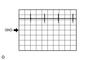
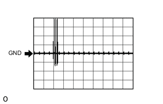
Using an oscilloscope, check waveform 2.
Note
The oscilloscope waveform shown in the illustration is an example for reference only. Noise, chattering, etc. are not shown.
Waveform 2 (Reference) Item Content Tester Connection K8-4 (CLG1) - K8-1 (E)
K8-3 (CG1B) - K8-1 (E)
K8-12 (CLG2) - K8-1 (E)
K8-11 (CG2B) - K8-1 (E)
Tool Setting 5 V/DIV., 500 ms/DIV. Condition Procedure:
-
Power switch off
-
All doors closed
-
Electrical key transmitter sub-assembly not inside vehicle
-
All doors locked through wireless operation
(electrical key transmitter sub-assembly brought outside detection area*)
-
*: For details about the entry function detection area, refer to Operation Check.
-
-
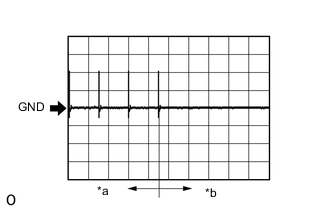
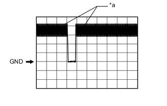
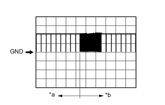
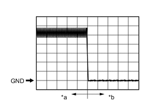
*a For 30 seconds after closing any door using the door outside handle *b 30 seconds or more have elapsed after closing any door using the door outside handle Using an oscilloscope, check waveform 3.
Note
The oscilloscope waveform shown in the illustration is an example for reference only. Noise, chattering, etc. are not shown.
Waveform 3 (Reference) Item Content Tester Connection K8-8 (CLG5) - K8-1 (E)
K8-7 (CG5B) - K8-1 (E)
K7-10 (CLG6) - K8-1 (E)
K7-9 (CG6B) - K8-1 (E)
Tool Setting 2 V/DIV., 500 ms/DIV. Condition Procedure:
-
Power switch off
-
Electrical key transmitter sub-assembly not inside vehicle
-
Within 30 seconds of closing any door using the door outside handle
-
-
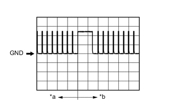
*a Driver door lock sensor not touched *b Driver door lock sensor touched Using an oscilloscope, check waveform 4.
Note
The oscilloscope waveform shown in the illustration is an example for reference only. Noise, chattering, etc. are not shown.
Waveform 4 (Reference) Item Content Tester Connection K7-8 (CLG7) - K8-1 (E)
K7-7 (CG7B) - K8-1 (E)
Tool Setting 2 V/DIV., 500 ms/DIV. Condition Procedure:
-
Door is closed
-
Power switch off
-
Electrical key transmitter sub-assembly not inside vehicle
-
Driver door lock sensor touched
-
-
Using an oscilloscope, check waveform 5.
Note
The oscilloscope waveform shown in the illustration is an example for reference only. Noise, chattering, etc. are not shown.
Waveform 5 (Reference) Item Content Tester Connection K7-6 (CLG8) - K8-1 (E)
K7-5 (CG8B) - K8-1 (E)
Tool Setting 2 V/DIV., 500 ms/DIV. Condition Procedure:
-
Power switch off
-
Electrical key transmitter sub-assembly brought outside vehicle
-
All doors closed
-
Luggage electrical key switch off → on
-
-
*a Checking for switch on signal at short intervals Using an oscilloscope, check waveform 6.
Note
The oscilloscope waveform shown in the illustration is an example for reference only. Noise, chattering, etc. are not shown.
Waveform 6 (Reference) Item Content Tester Connection K8-5 (TSW5) - K8-1 (E) Tool Setting 2 V/DIV., 500 ms/DIV. Condition Luggage electrical key switch off → on -
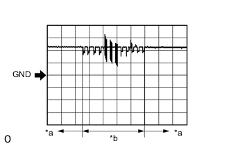
*a Before lock or unlock switch of electrical key transmitter sub-assembly pressed *b After lock or unlock switch of electrical key transmitter sub-assembly pressed Using an oscilloscope, check waveform 7.
Note
The oscilloscope waveform shown in the illustration is an example for reference only. Noise, chattering, etc. are not shown.
Waveform 7 (Reference) Item Content Tester Connection K7-1 (RCO) - K8-1 (E) Tool Setting 2 V/DIV., 500 ms/DIV. Condition Procedure:
-
Power switch off
-
Electrical key transmitter sub-assembly brought outside detection area but kept inside wireless function operational area
-
Lock or unlock switch of electrical key transmitter sub-assembly not pressed → pressed
-
-
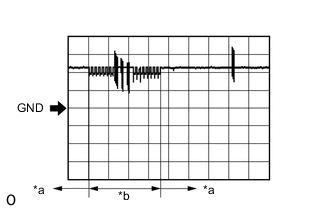
*a Before lock or unlock switch of electrical key transmitter sub-assembly pressed *b After lock or unlock switch of electrical key transmitter sub-assembly pressed Using an oscilloscope, check waveform 8.
Note
The oscilloscope waveform shown in the illustration is an example for reference only. Noise, chattering, etc. are not shown.
Waveform 8 (Reference) Item Content Tester Connection K7-3 (RDAM) - K8-1 (E) Tool Setting 5 V/DIV., 500 ms/DIV. Condition Procedure:
-
Power switch off
-
All doors locked
-
Electrical key transmitter sub-assembly not inside vehicle
-
Electrical key transmitter sub-assembly brought outside detection area but kept inside wireless function operational area
-
Lock or unlock switch of electrical key transmitter sub-assembly not pressed → pressed
-
-
*a Lock sensor not touched *b Lock sensor touched Using an oscilloscope, check waveform 9.
Note
The oscilloscope waveform shown in the illustration is an example for reference only. Noise, chattering, etc. are not shown.
Waveform 9 (Reference) Item Content Tester Connection K8-4 (CLG1) - K8-1 (E)
K8-12 (CLG2) - K8-1 (E)
Tool Setting 5 V/DIV., 40 ms/DIV. Condition Procedure:
-
Power switch off
-
Electrical key transmitter sub-assembly brought outside vehicle
-
All doors closed
-
All doors locked through wireless operation
(electrical key transmitter sub-assembly brought outside detection area*)
-
Lock sensor not touched → touched
-
*: For details about the entry function detection area, refer to Operation Check.
-
-
*a Unlock sensor not touched *b Unlock sensor touched Using an oscilloscope, check waveform 10.
Note
The oscilloscope waveform shown in the illustration is an example for reference only. Noise, chattering, etc. are not shown.
Waveform 10 (Reference) Item Content Tester Connection K8-4 (CLG1) - K8-1 (E)
K8-12 (CLG2) - K8-1 (E)
Tool Setting 5 V/DIV., 40 ms/DIV. Condition Procedure:
-
Power switch off
-
Electrical key transmitter sub-assembly brought outside vehicle
-
All doors locked
-
Electrical key transmitter sub-assembly not near the vehicle
-
Unlock sensor not touched → touched
-
-
-
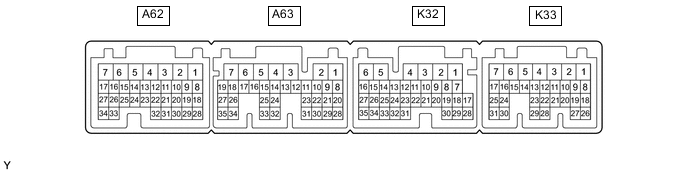
CHECK POWER MANAGEMENT CONTROL ECU
-
Disconnect the K32 and K33 connectors.
-
Measure the voltage and resistance according to the value(s) in the table below.
Tester Connection Input/Output Wiring Color Terminal Description Condition Specified Condition Related Data List Item K33-10 (STP) - Body ground Input R - Body ground Stop light switch signal Brake pedal depressed → Brake pedal released 9 V or higher → Below 1 V Stop Light Switch1 K33-7 (AM21) - K32-6 (E1) Input BE - BR Power source Power switch off 11 to 14 V - K32-1 (AM22) - K32-6 (E1) Input BE - BR Power source Power switch off 11 to 14 V - K33-12 (SLP) - K32-6 (E1) Input R - BR Steering lock position signal Steering locked 10 kΩ or higher Steering Unlock Switch K33-14 (P2) - K32-6 (E1) Input LG - BR P position signal Shift lever in P → Shift lever not in P 30 kΩ or higher → Below 200 Ω Shift P Signal K32-5 (E01) - Body ground - W-B - Body ground Ground Always Below 1 Ω - K33-5 (E02) - Body ground - W-B - Body ground Ground Always Below 1 Ω - K32-6 (E1) - Body ground - BR - Body ground Ground Always Below 1 Ω - K33-4 (E12) - Body ground - W-B - Body ground Ground Always Below 1 Ω - K32-16 (SPDI) - Body ground Input L - Body ground Vehicle speed signal Always 30 kΩ or higher Vehicle Speed Signal -
Reconnect the K32 and K33 power management control ECU connectors.
-
Measure the voltage and check for pulses according to the value(s) in the table below.
Tester Connection Input/Output Wiring Color Terminal Description Condition Specified Condition Related Data List Item K33-10 (STP) - K32-6 (E1) Input R - BR Stop light switch signal Brake pedal depressed → Brake pedal released 9 V or higher → 1 V or less Stop Light Switch1 K33-12 (SLP) - K32-6 (E1) Input R - BR Steering lock position signal Steering locked → Steering unlocked 11 to 14 V → 1.5 V or less Steering Unlock Switch K33-14 (P2) - K32-6 (E1) Input LG - BR LG - BR Shift lever in P → Shift lever not in P 9 V or higher → 2.76 V or less Shift P Signal K32-16 (SPDI) - K32-6 (E1) Input L - BR Vehicle speed signal Vehicle being driven at approx. 5 km/h (3 mph) Pulse generation
(See waveform 1)
Vehicle Speed Signal -
Using an oscilloscope, check the signal waveform of the ECU.
-
Waveform 1
Tester Connection K32-16 (SPDI) - K32-6 (E1) Tool Setting 5 V/DIV., 10 ms./DIV. Vehicle Condition Vehicle being driven at approx. 5 km/h (3 mph) Tech Tips
The wavelength becomes shorter as the vehicle speed increases.
-
-
-
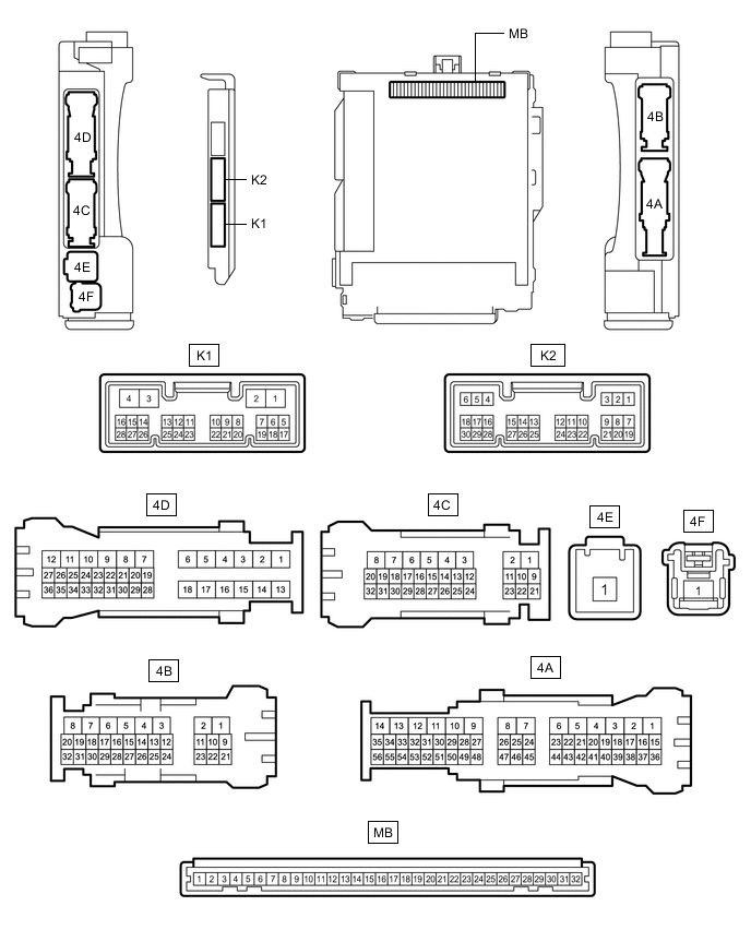
CHECK INSTRUMENT PANEL JUNCTION BLOCK ASSEMBLY AND MAIN BODY ECU (MULTIPLEX NETWORK BODY ECU)
-
Remove the main body ECU (multiplex network body ECU) from the instrument panel junction block assembly.
-
Measure the voltage and resistance according to the value(s) in the table below.
Tester Connection Input/Output Wiring Color Terminal Description Condition Specified Condition Related Data List Item MB-11 (GND1) - Body ground - - Ground Always Below 1 Ω - MB-31 (BECU) - Body ground Input - Auxiliary battery power supply (for CPU) Power switch off 11 to 14 V - K2-6 (FLCY) - Body ground Input V - Body ground Front door LH courtesy light switch input Front door LH closed → open 10 kΩ or higher → Below 1 Ω FL Door Courtesy SW K2-27 (FRCY) - Body ground Input V - Body ground Front door RH courtesy light switch input Front door RH closed → open 10 kΩ or higher → Below 1 Ω FR Door Courtesy SW MB-13 (LCTY) - Body ground Input - Rear door LH courtesy light switch input Rear door LH closed → open 10 kΩ or higher → Below 1 Ω RL Door Courtesy SW MB-2 (RCTY) - Body ground Input - Rear door RH courtesy light switch input Rear door RH closed → open 10 kΩ or higher → Below 1 Ω RR Door Courtesy SW -
Install the main body ECU (multiplex network body ECU) to the instrument panel junction block assembly.
-
Measure the voltage and check for pulses according to the value(s) in the table below.
Tester Connection Input/Output Wiring Color Terminal Description Condition Specified Condition Related Data List Item 4B-26 (LSFL) - Body ground Input G - Body ground Front door LH unlock detection switch input Front door LH locked → unlocked Pulse generation
(See waveform 1)
FL Door Lock Pos 4B-27 (LSFR) - Body ground Input B - Body ground Front door RH unlock detection switch input Front door RH locked → unlocked Pulse generation
(See waveform 1)
FR Door Lock Pos 4B-23 (LSWL) - Body ground Input L - Body ground Rear door LH unlock detection switch input Rear door LH locked → unlocked Pulse generation
(See waveform 1)
RL-Door Lock Pos SW K1-2 (LSWR) - Body ground Input W - Body ground Rear door RH unlock detection switch input Rear door RH locked → unlocked Pulse generation
(See waveform 1)
RR-Door Lock Pos SW K2-6 (FLCY) - Body ground Input V - Body ground Front door LH courtesy light switch input Front door LH closed → open Pulse generation
(See waveform 2)
FL Door Courtesy SW K2-27 (FRCY) - Body ground Input V - Body ground Front door RH courtesy light switch input Front door RH closed → open Pulse generation
(See waveform 2)
FR Door Courtesy SW 4D-25 (LCTY) - Body ground Input BE - Body ground Rear door LH courtesy light switch input Rear door LH closed → open Pulse generation
(See waveform 2)
RL Door Courtesy SW 4B-17 (RCTY) - Body ground Input BE - Body ground Rear door RH courtesy light switch input Rear door RH closed → open Pulse generation
(See waveform 2)
RR Door Courtesy SW 4D-16 (LGCY) - Body ground Input G - Body ground Luggage door courtesy light switch input Luggage compartment door closed → opened Pulse generation
(See waveform 2)
Luggage Courtesy SW 4C-28 (BZR) - Body ground Output G - Body ground Wireless buzzer signal output Procedure:
-
Power switch off
-
All doors closed
-
Lock switch of electrical key transmitter sub-assembly not pressed → pressed
Below 1 V → pulse generation - -
-
*a Door locked *b Door unlocked Using an oscilloscope, check waveform 1.
Note
The oscilloscope waveform shown in the illustration is an example for reference only. Noise, chattering, etc. are not shown.
Waveform 1 (Reference) Item Content Tester Connection 4B-26 (LSFL) - Body ground
4B-27 (LSFR) - Body ground
4B-23 (LSWL) - Body ground
K1-2 (LSWR) - Body ground
Tool Setting 2 V/DIV., 200 ms/DIV. Condition Door locked → unlocked -

*a Door closed *b Door open Using an oscilloscope, check waveform 2.
Note
The oscilloscope waveform shown in the illustration is an example for reference only. Noise, chattering, etc. are not shown.
Waveform 2 (Reference) Item Content Tester Connection K2-6 (FLCY) - Body ground
K2-27 (FRCY) - Body ground
4D-25 (LCTY) - Body ground
4B-17 (RCTY) - Body ground
4D-16 (LGCY) - Body ground
Tool Setting 2 V/DIV., 200 ms/DIV. Condition Door closed → opened
-