ENTRY AND START SYSTEM(for Entry Function) Entry Exterior Alarm and Answer-back Buzzer do not Sound
DESCRIPTION
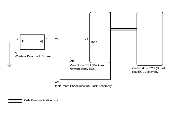
The entry and start system (for Entry Function) uses the wireless door lock buzzer to perform various vehicle exterior warnings. When the conditions of each warning are met, the certification ECU (smart key ECU assembly) sends a buzzer activation request signal to the main body ECU (multiplex network body ECU) via CAN communication and the buzzer sounds.
WIRING DIAGRAM
CAUTION / NOTICE / HINT
Note
-
The entry and start system (for Entry Function) uses the LIN communication system and CAN communication system. Inspect the communication function by following How to Proceed with Troubleshooting. Troubleshoot the entry and start system (for Entry Function) after confirming that the communication systems are functioning properly.
-
When using the GTS with the power switch off, connect the GTS to the DLC3 and turn a courtesy light switch on and off at intervals of 1.5 seconds or less until communication between the GTS and the vehicle begins. Then select Model Code "KEY REGIST" under manual mode and enter the following menus: Body Electrical / Entry&Start(CAN). While using the GTS, periodically turn a courtesy light switch on and off at intervals of 1.5 seconds or less to maintain communication between the GTS and the vehicle.
-
Before replacing the certification ECU (smart key ECU assembly) or main body ECU (multiplex network body ECU), refer to entry and start system (for Entry Function) Precaution.
-
After repair, confirm that no DTCs are output by performing "DTC Output Confirmation Operation".
PROCEDURE
-
CHECK CUSTOMIZE SETTING (WIRELESS BUZZER RESP)
-
Connect the GTS to the DLC3.
-
Turn the power switch on (IG).
-
Turn the GTS on.
-
Enter the following menus: Customize Setting / Wireless Door Lock.
Wireless Door LockTester Display Description Default Setting ECU Wireless Buzzer Resp Wireless buzzer response ON 0:OFF,1:ON Main body ECU (multiplex network body ECU) Result Result Proceed to "ON" is displayed A "OFF" is displayed B
B 
PERFORM CUSTOMIZE SETTING Click here
A 
-
-
CHECK WIRELESS DOOR LOCK CONTROL SYSTEM
-
Check that the wireless door lock functions operate normally.
Result Result Proceed to Wireless door lock function does not operate normally A Wireless door lock function operates normally B
B
GO TO PROBLEM SYMPTOMS TABLE Click here
A
-
-
READ VALUE USING GTS (EACH UNLOCK DETECTION SWITCH)
-
Connect the GTS to the DLC3.
-
Turn the power switch on (IG).
-
Turn the GTS on.
-
Enter the following menus: Body Electrical / Main Body / Data List.
-
Read the Data List according to the display on the GTS.
Body Electrical > Main Body > Data ListTester Display Measurement Item Range Normal Condition Diagnostic Note FR Door Lock Pos Front door RH unlock detection switch signal UNLOCK or LOCK UNLOCK: Front door RH unlocked
LOCK: Front door RH locked
- FL Door Lock Pos Front door LH unlock detection switch signal UNLOCK or LOCK UNLOCK: Front door LH unlocked
LOCK: Front door LH locked
- RR-Door Lock Pos SW Rear door RH unlock detection switch signal ON or OFF ON: Rear door RH unlocked
OFF: Rear door RH locked
- RL-Door Lock Pos SW Rear door LH unlock detection switch signal ON or OFF ON: Rear door LH unlocked
OFF: Rear door LH locked
-
Body Electrical > Main Body > Data ListTester Display FR Door Lock Pos FL Door Lock Pos RR-Door Lock Pos SW RL-Door Lock Pos SW OK The GTS display changes correctly in response to the lock/unlock operation. Result Proceed to OK NG
NG
GO TO LIGHTING SYSTEM (Proceed to Door Unlock Detection Switch Circuit) Click here
OK
-
-
PERFORM ACTIVE TEST USING GTS (WIRELESS BUZZER)
-
Connect the GTS to the DLC3.
-
Turn the power switch on (IG).
-
Turn the GTS on.
-
Enter the following menus: Body Electrical / Main Body / Active Test.
-
Perform Active Test according to the display on the GTS.
Body Electrical > Main Body > Active TestTester Display Measurement Item Control Range Diagnostic Note Wireless Buzzer Wireless door lock buzzer OFF/ON -
Body Electrical > Main Body > Active TestTester Display Wireless Buzzer Result Result Proceed to Wireless buzzer does not sound A Wireless buzzer sounds B
B
REPLACE CERTIFICATION ECU (SMART KEY ECU ASSEMBLY)
A
-
-
CHECK WIRELESS DOOR LOCK BUZZER
-
Disconnect the A14 wireless door lock buzzer connector.
-
Perform the Active Test using the GTS and sound the wireless door lock buzzer.
Body Electrical > Main Body > Active TestTester Display Measurement Item Control Range Diagnostic Note Wireless Buzzer Wireless door lock buzzer OFF/ON -
Body Electrical > Main Body > Active TestTester Display Wireless Buzzer -
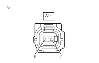
*a Front view of wire harness connector
(to Wireless Door Lock Buzzer)
While performing the Active Test, measure the voltage between the terminals of the wireless door lock buzzer.
Standard Voltage Tester Connection Condition Specified Condition A14-1 (+B) - A14-2 (E) Active Test Wireless Buzzer ON Pulse generation
(frequency: 2 kHz, high voltage: 11 to 14 V, low voltage: below 1 V)
Active Test Wireless Buzzer OFF Below 1 V Result Proceed to OK NG
OK
REPLACE WIRELESS DOOR LOCK BUZZER Click here
NG
-
-
CHECK HARNESS AND CONNECTOR (WIRELESS DOOR LOCK BUZZER - MAIN BODY ECU (MULTIPLEX NETWORK BODY ECU) AND BODY GROUND)
-
Remove the main body ECU (multiplex network body ECU) from the instrument panel junction block assembly.
-
Reconnect the 4C instrument panel junction block assembly connector.
-
Measure the resistance according to the value(s) in the table below.
Standard Resistance Tester Connection Condition Specified Condition A14-1 (+B) - MB-21 (BZR) Always Below 1 Ω A14-2 (E) - Body ground Always Below 1 Ω A14-1 (+B) or MB-21 (BZR) - Body ground Always 10 kΩ or higher Result Proceed to OK NG
OK
REPLACE MAIN BODY ECU (MULTIPLEX NETWORK BODY ECU) Click here
NG
-
-
CHECK HARNESS AND CONNECTOR (WIRELESS DOOR LOCK BUZZER - INSTRUMENT PANEL JUNCTION BLOCK ASSEMBLY)
-
Disconnect the 4C instrument panel junction block assembly connector.
-
Measure the resistance according to the value(s) in the table below.
Standard Resistance Tester Connection Condition Specified Condition A14-1 (+B) - 4C-28 (BZR) Always Below 1 Ω A14-1 (+B) or 4C-28 (BZR) - Body ground Always 10 kΩ or higher Result Proceed to OK NG
OK
REPLACE INSTRUMENT PANEL JUNCTION BLOCK ASSEMBLY Click here
NG
REPAIR OR REPLACE HARNESS OR CONNECTOR
-