Click here
-
CHECK INSTRUMENT PANEL JUNCTION BLOCK ASSEMBLY AND MAIN BODY ECU (MULTIPLEX NETWORK BODY ECU)
-
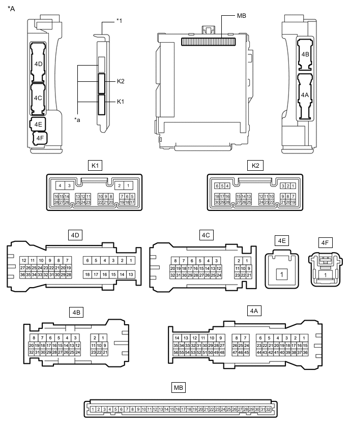
*A Main Body ECU (Multiplex Network Body ECU) with 3 Connectors - - *1 Main Body ECU (Multiplex Network Body ECU) - - *a 3 Connectors - - Disconnect the MB main body ECU (multiplex network body ECU) connector.
-
Measure the voltage and resistance according to the value(s) in the table below.
Tip:Measure the values on the wire harness side with the connectors disconnected.
Tester Connection Wiring Color Terminal Description Condition Specified Condition MB-11 (GND1) - Body ground - Ground Always Below 1 Ω MB-31 (BECU) - Body ground - Auxiliary battery power supply Power switch off 11 to 14 V MB-30 (ACC) - Body ground - ACC power supply Power switch on (ACC) 11 to 14 V MB-30 (ACC) - Body ground - ACC power supply Power switch off Below 1 V MB-32 (IG) - Body ground - IG power supply Power switch on (IG) 11 to 14 V MB-32 (IG) - Body ground - IG power supply Power switch off Below 1 V If the result is not as specified, there may be a malfunction in the wire harness.
-
Reconnect the MB main body ECU (multiplex network body ECU) connector.
-
Measure the voltage and check for pulses according to the value(s) in the table below.
Tester Connection Wiring Color Terminal Description Condition Specified Condition 4B-3 (ACT-) - Body ground*1
4B-2 (ACT-) - Body ground*2
L - Body ground Door lock motor unlock drive output (except driver door) Door control switch (multiplex network master switch assembly) or driver door key cylinder off Below 1 V 4B-3 (ACT-) - Body ground*1
4B-2 (ACT-) - Body ground*2
L - Body ground Door lock motor unlock drive output (except driver door) Door control switch (multiplex network master switch assembly) or driver door key cylinder unlocked 11 to 14 V 4D-10 (ACT-) - Body ground P - Body ground Door lock motor unlock drive output (except driver door) Door control switch (multiplex network master switch assembly) or driver door key cylinder off Below 1 V 4D-10 (ACT-) - Body ground P - Body ground Door lock motor unlock drive output (except driver door) Door control switch (multiplex network master switch assembly) or driver door key cylinder unlocked 11 to 14 V 4B-4 (ACT-) - Body ground V - Body ground Door lock motor unlock drive output (except driver door) Door control switch (multiplex network master switch assembly) or driver door key cylinder off Below 1 V 4B-4 (ACT-) - Body ground V - Body ground Door lock motor unlock drive output (except driver door) Door control switch (multiplex network master switch assembly) or driver door key cylinder unlocked 11 to 14 V 4B-2 (ACTD) - Body ground*1
4B-3 (ACTD) - Body ground*2
L - Body ground Door lock motor unlock drive output (for driver door) Door control switch (multiplex network master switch assembly) or driver door key cylinder off Below 1 V 4B-2 (ACTD) - Body ground*1
4B-3 (ACTD) - Body ground*2
L - Body ground Door lock motor unlock drive output (for driver door) Door control switch (multiplex network master switch assembly) or driver door key cylinder unlocked 11 to 14 V 4D-7 (ACT+) - Body ground R - Body ground Door lock motor lock drive output (all doors) Door control switch (multiplex network master switch assembly) or driver door key cylinder off Below 1 V 4D-7 (ACT+) - Body ground R - Body ground Door lock motor lock drive output (all doors) Door control switch (multiplex network master switch assembly) or driver door key cylinder locked 11 to 14 V 4D-8 (ACT+) - Body ground SB - Body ground Door lock motor lock drive output (all doors) Door control switch (multiplex network master switch assembly) or driver door key cylinder off Below 1 V 4D-8 (ACT+) - Body ground SB - Body ground Door lock motor lock drive output (all doors) Door control switch (multiplex network master switch assembly) or driver door key cylinder locked 11 to 14 V 4B-5 (ACT+) - Body ground GR - Body ground Door lock motor lock drive output (all doors) Door control switch (multiplex network master switch assembly) or driver door key cylinder off Below 1 V 4B-5 (ACT+) - Body ground GR - Body ground Door lock motor lock drive output (all doors) Door control switch (multiplex network master switch assembly) or driver door key cylinder locked 11 to 14 V 4B-6 (ACT+) - Body ground R - Body ground Door lock motor lock drive output (all doors) Door control switch (multiplex network master switch assembly) or driver door key cylinder off Below 1 V 4B-6 (ACT+) - Body ground R - Body ground Door lock motor lock drive output (all doors) Door control switch (multiplex network master switch assembly) or driver door key cylinder locked 11 to 14 V K2-27 (FRCY) - Body ground V - Body ground Front door courtesy light switch RH input Front door RH open Below 1 V K2-27 (FRCY) - Body ground V - Body ground Front door courtesy light switch RH input Front door RH closed 11 to 14 V K2-6 (FLCY) - Body ground V - Body ground Front door courtesy light switch LH input Front door LH open Below 1 V K2-6 (FLCY) - Body ground V - Body ground Front door courtesy light switch LH input Front door LH closed 11 to 14 V 4D-25 (LCTY) - Body ground BE - Body ground Rear door courtesy light switch LH input Rear door LH open Below 1 V 4D-25 (LCTY) - Body ground BE - Body ground Rear door courtesy light switch LH input Rear door LH closed Pulse generation 4B-17 (RCTY) - Body ground BE - Body ground Rear door courtesy light switch RH input Rear door RH open Below 1 V 4B-17 (RCTY) - Body ground BE - Body ground Rear door courtesy light switch RH input Rear door RH closed Pulse generation 4B-25 (L1) - Body ground G - Body ground*1
L - Body ground*2
Door control switch input Door control switch locked Below 1 V 4B-25 (L1) - Body ground G - Body ground*1
L - Body ground*2
Door control switch input Door control switch off Pulse generation 4B-24 (UL1) - Body ground Y - Body ground*1
LG - Body ground*2
Door control switch input Door control switch unlocked Below 1 V 4B-24 (UL1) - Body ground Y - Body ground*1
LG - Body ground*2
Door control switch input Door control switch off Pulse generation K2-29 (L2) - Body ground L - Body ground*1
G - Body ground*2
Driver door key-linked lock input Driver door key cylinder turned to lock position Below 1 V K2-29 (L2) - Body ground L - Body ground*1
G - Body ground*2
Driver door key-linked lock input Driver door key cylinder off Pulse generation K2-2 (UL3) - Body ground LG - Body ground*1
Y - Body ground*2
Driver door key-linked unlock input Driver door key cylinder turned to unlock position Below 1 V K2-2 (UL3) - Body ground LG - Body ground*1
Y - Body ground*2
Driver door key-linked unlock input Driver door key cylinder off Pulse generation 4B-26 (LSFL) - Body ground G - Body ground Front door LH unlock detection switch input Front door LH unlocked Below 1 V 4B-26 (LSFL) - Body ground G - Body ground Front door LH unlock detection switch input Front door LH locked Pulse generation 4B-27 (LSFR) - Body ground B - Body ground Front door RH unlock detection switch input Front door RH unlocked Below 1 V 4B-27 (LSFR) - Body ground B - Body ground Front door RH unlock detection switch input Front door RH locked Pulse generation K1-2 (LSWR) - Body ground W - Body ground Rear door RH unlock detection switch input Rear door RH unlocked Below 1 V K1-2 (LSWR) - Body ground W - Body ground Rear door RH unlock detection switch input Rear door RH locked Pulse generation 4B-23 (LSWL) - Body ground L - Body ground Rear door LH unlock detection switch input Rear door LH unlocked Below 1 V 4B-23 (LSWL) - Body ground L - Body ground Rear door LH unlock detection switch input Rear door LH locked Pulse generation 4D-16 (LGCY) - Body ground G - Body ground Luggage door courtesy light switch input Luggage compartment door open Below 1 V 4D-16 (LGCY) - Body ground G - Body ground Luggage door courtesy light switch input Luggage compartment door closed 11 to 14 V 4D-1 (TR+) - Body ground B - Body ground Luggage compartment door lock motor unlock drive output Luggage compartment door opener switch (open switch) pushed 11 to 14 V 4D-1 (TR+) - Body ground B - Body ground Luggage compartment door lock motor unlock drive output Luggage compartment door opener switch (open switch) not pushed Below 1 V
-
*1: for LHD
-
*2: for RHD
If the result is not as specified, the main body ECU (multiplex network body ECU) or instrument panel junction block assembly may be malfunctioning.
-
-
-
CHECK DOUBLE LOCK DOOR CONTROL RELAY ASSEMBLY (w/ Double Locking System)
-

Disconnect the K42 double lock door control relay assembly connector.
-
Measure the voltage and resistance according to the value(s) in the table below.
Tip:Measure the values on the wire harness side with the connector disconnected.
Tester Connection Wiring Color Terminal Description Condition Specified Condition K42-1 (+B) - Body ground W - Body ground Auxiliary battery power supply Power switch off 11 to 14 V K42-7 (CPUB) - Body ground LG - Body ground Auxiliary battery power supply Power switch off 11 to 14 V K42-14 (GND) - Body ground W-B - Body ground Ground Always Below 1 Ω If the result is not as specified, there may be a malfunction in the wire harness.
-
Reconnect the K42 double lock door control relay assembly connector.
-
Measure the voltage and check for pulses according to the value(s) in the table below.
Tester Connection Wiring Color Terminal Description Condition Specified Condition K42-5 (DLPD) - Body ground G - Body ground Front RH double lock position switch input Double lock unset Pulse generation K42-5 (DLPD) - Body ground G - Body ground Front RH double lock position switch input Double lock set Below 1 V K42-6 (DLPP) - Body ground GR - Body ground Front LH double lock position switch input Double lock unset Pulse generation K42-6 (DLPP) - Body ground GR - Body ground Front LH double lock position switch input Double lock set Below 1 V K42-11 (DLPR) - Body ground BE - Body ground Rear RH double lock position switch input Double lock unset Pulse generation K42-11 (DLPR) - Body ground BE - Body ground Rear RH double lock position switch input Double lock set Below 1 V K42-12 (DLPL) - Body ground L - Body ground Rear LH double lock position switch input Double lock unset Pulse generation K42-12 (DLPL) - Body ground L - Body ground Rear LH double lock position switch input Double lock set Below 1 V K42-3 (ACTS) - Body ground V - Body ground All door double lock motor set on output Double lock unset Below 1 V K42-3 (ACTS) - Body ground V - Body ground All door double lock motor set on output Double lock set 11 to 14 V K42-4 (ACTR) - Body ground P - Body ground All door double lock motor set off output Double lock set Below 1 V K42-4 (ACTR) - Body ground P - Body ground All door double lock motor set off output Double lock unset 11 to 14 V If the result is not as specified, the double lock door control relay assembly may be malfunctioning.
-