CAN COMMUNICATION SYSTEM TERMINALS OF ECU
Note
-
After turning the power switch off, waiting time may be required before disconnecting the cable from the negative (-) auxiliary battery terminal. Therefore, make sure to read the disconnecting the cable from the negative (-) auxiliary battery terminal notices before proceeding with work.
-
Before measuring the resistance of the CAN bus, turn the power switch off and leave the vehicle for 1 minute or more without operating the key or any switches, or opening or closing the doors. After that, disconnect the cable from the negative (-) auxiliary battery terminal and leave the vehicle for 1 minute or more before measuring the resistance.
-
This section describes the standard values for all CAN related components.
Tech Tips
-
The systems (ECUs and sensors) that use CAN communication vary depending on the vehicle and optional equipment. Check which systems (ECUs and sensors) are installed to the vehicle.
-
Operating the power switch, any other switches or a door triggers related ECU and sensor communication on the CAN. This communication will cause the resistance value to change.
-
Even after DTCs are cleared, if a DTC is stored again after driving the vehicle for a while, the malfunction may be occurring due to vibration of the vehicle. In such a case, wiggling the ECUs or wire harness while performing the inspection below may help determine the cause of the malfunction.
-
NO. 1 CAN JUNCTION CONNECTOR (for LHD)
-
Check the No. 1 CAN junction connector.
-
Connection diagram
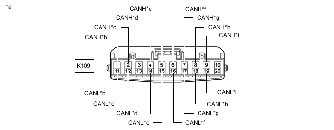
*a Front view of wire harness connector
(to No. 1 CAN Junction Connector)
*b to No. 2 CAN Junction Connector *c to Combination Meter Assembly *d to Central Gateway ECU (Network Gateway ECU) *e to Air Conditioning Amplifier Assembly *f to Stereo Component Equalizer Assembly
(w/ ASC System)
*g to Certification ECU (Smart Key ECU Assembly) *h to Hybrid Vehicle Control ECU Assembly *i to Power Steering ECU Assembly - - -
Check the connection diagram of the components which are connected to the No. 1 CAN junction connector.
Terminal No. (Symbol) Wiring Color Connected to K109-1 (CANH) L No. 2 CAN junction connector
(for Bus 2)
K109-11 (CANL) B K109-2 (CANH) LG Combination meter assembly
(for Bus 2)
K109-12 (CANL) B K109-4 (CANH) BE Central gateway ECU (network gateway ECU)
(for Bus 2)
K109-14 (CANL) B K109-5 (CANH) P Air conditioning amplifier assembly
(for Bus 2)
K109-15 (CANL) B K109-6 (CANH) V Stereo component equalizer assembly*
(for Bus 2)
K109-16 (CANL) B K109-7 (CANH) W Certification ECU (smart key ECU assembly)
(for Bus 2)
K109-17 (CANL) B K109-8 (CANH) SB Hybrid vehicle control ECU assembly
(for Bus 2)
K109-18 (CANL) B K109-9 (CANH) G Power steering ECU assembly
(for Bus 2)
K109-19 (CANL) B
-
*: w/ ASC System
-
-
-
-
NO. 2 CAN JUNCTION CONNECTOR (for LHD)
-
Check the No. 2 CAN junction connector.
-
Connection diagram
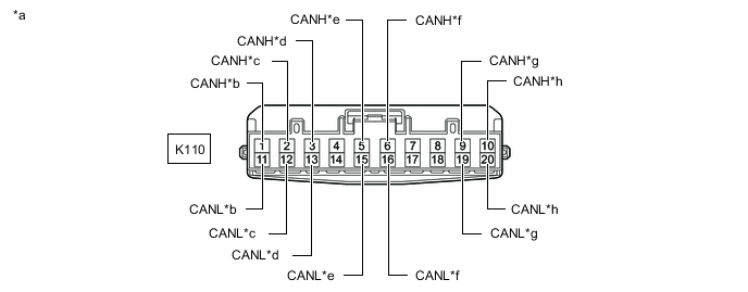
*a Front view of wire harness connector
(to No. 2 CAN Junction Connector)
*b to No. 1 CAN Junction Connector *c to Main Body ECU (Multiplex Network Body ECU) *d to ECM *e to Airbag Sensor Assembly *f to Yaw Rate Sensor *g to Steering Sensor *h to Skid Control ECU Assembly -
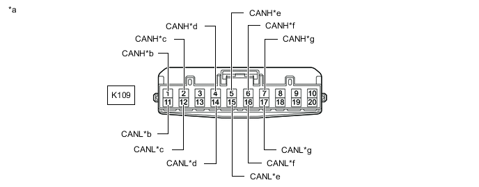
Check the connection diagram of the components which are connected to the No. 2 CAN junction connector.
Terminal No. (Symbol) Wiring Color Connected to K110-1 (CANH) L No. 1 CAN junction connector
(for Bus 2)
K110-11 (CANL) B K110-2 (CANH) Y Main body ECU (multiplex network body ECU)
(for Bus 2)
K110-12 (CANL) B K110-3 (CANH) R ECM
(for Bus 2)
K110-13 (CANL) B K110-5 (CANH) BE Airbag sensor assembly
(for Bus 2)
K110-15 (CANL) B K110-6 (CANH) G Yaw rate sensor
(for Bus 2)
K110-16 (CANL) B K110-9 (CANH) P Steering sensor
(for Bus 2)
K110-19 (CANL) B K110-10 (CANH) SB Skid control ECU assembly
(for Bus 2)
K110-20 (CANL) B
-
-
-
NO. 3 CAN JUNCTION CONNECTOR (for LHD)
-
Check the No. 3 CAN junction connector.
-
Connection diagram
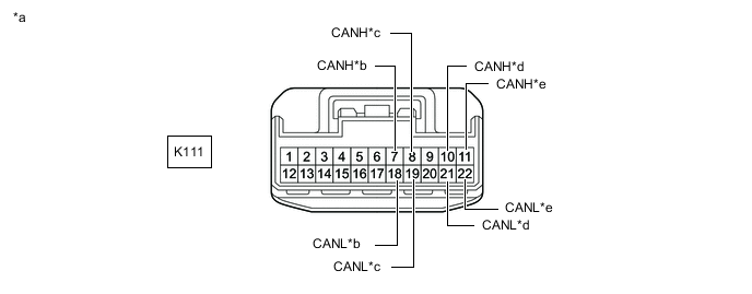
*a Front view of wire harness connector
(to No. 3 CAN Junction Connector)
*b to No. 15 Junction Connector *c to Multiplex Tilt and Telescopic ECU
(w/ Power Tilt and Power Telescopic System)
*d to Outer Mirror Control ECU Assembly (for Front Passenger Side)
(w/ Seat Position Memory System)
*e to Junction Terminal - - -
Check the connection diagram of the components which are connected to the No. 3 CAN junction connector.
Terminal No. (Symbol) Wiring Color Connected to K111-7 (CANH) LG No. 15 junction connector
(for Sub bus 1)
K111-18 (CANL) B K111-8 (CANH) G Multiplex tilt and telescopic ECU*1
(for Sub bus 1)
K111-19 (CANL) B K111-10 (CANH) W Outer mirror control ECU assembly (for front passenger side)*2
(for Sub bus 1)
K111-21 (CANL) B K111-11 (CANH) P Junction terminal
(for Sub bus 1)
K111-22 (CANL) B
-
*1: w/ Power Tilt and Power Telescopic System
-
*2: w/ Seat Position Memory System
-
-
-
-
NO. 8 CAN JUNCTION CONNECTOR (for LHD)
-
Check the No. 8 CAN junction connector.
-
Connection diagram
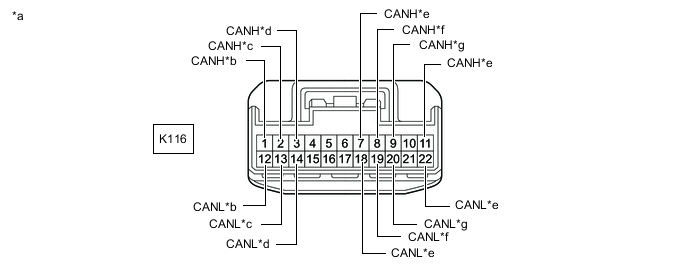
*a Front view of wire harness connector
(to No. 8 CAN Junction Connector)
*b to Hybrid Vehicle Control ECU Assembly *c to Skid Control ECU Assembly *d to ECM *e to Central Gateway ECU (Network Gateway ECU) *f to Telematics Transceiver
(w/ Telematics Transceiver)
*g to Radio Receiver Assembly
(w/ Navigation System or Audio and Visual System)
- - -
Check the connection diagram of the components which are connected to the No. 8 CAN junction connector.
Terminal No. (Symbol) Wiring Color Connected to K116-1 (CANH) R Hybrid vehicle control ECU assembly
(for Sub bus 15)
K116-12 (CANL) B K116-2 (CANH) W Skid control ECU assembly
(for Sub bus 15)
K116-13 (CANL) B K116-3 (CANH) P ECM
(for Sub bus 15)
K116-14 (CANL) B K116-7 (CANH) R Central gateway ECU (network gateway ECU)
(for Bus 3)
K116-18 (CANL) B K116-8 (CANH) LG Telematics transceiver*1
(for Bus 3)
K116-19 (CANL) B K116-9 (CANH) BE Radio receiver assembly*2
(for Bus 3)
K116-20 (CANL) B K116-11 (CANH) V Central gateway ECU (network gateway ECU)
(for Bus 3)
K116-22 (CANL) B
-
*1: w/ Telematics Transceiver
-
*2: w/ Navigation System or Audio and Visual System
-
-
-
-
NO. 9 CAN JUNCTION CONNECTOR (for LHD)
-
Check the No. 9 CAN junction connector.
Tech Tips
Connectors that connect to the CAN junction connector can be distinguished by the color of their CAN bus lines. When the connectors have been disconnected from the CAN junction connector, reconnecting the connectors to non-original positions on the CAN junction connector does not affect system performance. However, it is preferred to reconnect the connectors to their original positions to avoid negative effects on the wiring such as tension on the wire harnesses, and to make future maintenance easier.
-
Connection diagram
*a Component with harness connected
(No. 9 CAN Junction Connector)
*b to No. 13 CAN Junction Connector *c to Central Gateway ECU (Network Gateway ECU) *d to Blind Spot Monitor Sensor LH
(w/ Blind Spot Monitor System)
-
Check the connection diagram of the components which are connected to the No. 9 CAN junction connector.
Terminal No. (Symbol) Wiring Color Connected to Q63-1 (CANH) BE No. 13 CAN junction connector
(for Bus 5)
Q63-2 (CANL) B Q64-1 (CANH) GR Central gateway ECU (network gateway ECU)
(for Bus 5)
Q64-2 (CANL) B Q65-1 (CANH) R Blind spot monitor sensor LH*
(for Bus 5)
Q65-2 (CANL) B
-
*: w/ Blind Spot Monitor System
-
-
-
-
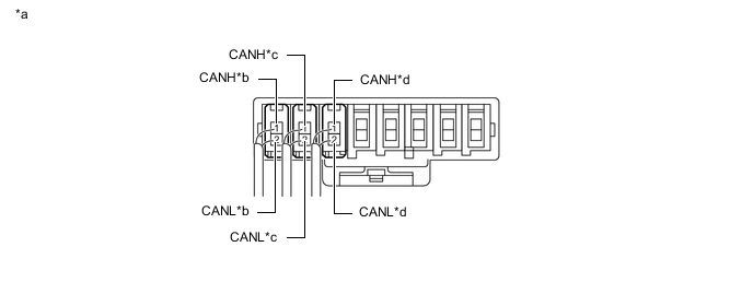
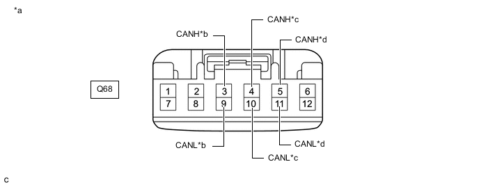
NO. 10 CAN JUNCTION CONNECTOR (for LHD)
-
Check the No. 10 CAN junction connector.
-
Connection diagram
*a Front view of wire harness connector
(to No. 10 CAN Junction Connector)
*b to No. 13 CAN Junction Connector *c to Central Gateway ECU (Network Gateway ECU) *d to Blind Spot Monitor Sensor LH
(w/ Blind Spot Monitor System)
-
Check the connection diagram of the components which are connected to the No. 10 CAN junction connector.
Terminal No. (Symbol) Wiring Color Connected to Q68-3 (CANH) BE No. 13 CAN junction connector
(for Bus 5)
Q68-9 (CANL) B Q68-4 (CANH) GR Central gateway ECU (network gateway ECU)
(for Bus 5)
Q68-10 (CANL) B Q68-5 (CANH) R Blind spot monitor sensor LH*
(for Bus 5)
Q68-11 (CANL) B
-
*: w/ Blind Spot Monitor System
-
-
-
-
NO. 12 CAN JUNCTION CONNECTOR (for LHD)
-
Check the No. 12 CAN junction connector.
Tech Tips
Connectors that connect to the CAN junction connector can be distinguished by the color of their CAN bus lines. When the connectors have been disconnected from the CAN junction connector, reconnecting the connectors to non-original positions on the CAN junction connector does not affect system performance. However, it is preferred to reconnect the connectors to their original positions to avoid negative effects on the wiring such as tension on the wire harnesses, and to make future maintenance easier.
-
Connection diagram
*a Component with harness connected
(No. 12 CAN Junction Connector)
*b to Hybrid Vehicle Control ECU Assembly *c to No. 13 CAN Junction Connector *d to Absorber Control ECU
(w/ AVS System)
-
Check the connection diagram of the components which are connected to the No. 12 CAN junction connector.
Terminal No. (Symbol) Wiring Color Connected to K147-1 (CANH) GR Hybrid vehicle control ECU assembly
(for Bus 5)
K147-2 (CANL) B K148-1 (CANH) LG No. 13 CAN junction connector
(for Bus 5)
K148-2 (CANL) B K149-1 (CANH) SB Absorber control ECU*
(for Bus 5)
K149-2 (CANL) B
-
*: w/ AVS System
-
-
-
-
NO. 13 CAN JUNCTION CONNECTOR (for LHD)
-
Check the No. 13 CAN junction connector.
Tech Tips
Connectors that connect to the CAN junction connector can be distinguished by the color of their CAN bus lines. When the connectors have been disconnected from the CAN junction connector, reconnecting the connectors to non-original positions on the CAN junction connector does not affect system performance. However, it is preferred to reconnect the connectors to their original positions to avoid negative effects on the wiring such as tension on the wire harnesses, and to make future maintenance easier.
-
Connection diagram
*a Component with harness connected
(No. 13 CAN Junction Connector)
*b to No. 12 CAN Junction Connector *c to Forward Recognition Camera
(w/ Lexus Safety System +)
*d to Millimeter Wave Radar Sensor Assembly
(w/ Lexus Safety System +)
*e to Clearance Warning ECU Assembly
(w/ LEXUS Parking Assist-sensor System)
*f to No. 9 CAN Junction Connector or No. 10 CAN Junction Connector *g to Driving Support ECU Assembly
(w/ Lexus Safety System +)
- - -
Check the connection diagram of the components which are connected to the No. 13 CAN junction connector.
Terminal No. (Symbol) Wiring Color Connected to K151-1 (CANH) LG No. 12 CAN junction connector
(for Bus 5)
K151-2 (CANL) B K152-1 (CANH) R Forward recognition camera*1
(for Bus 5)
K152-2 (CANL) B K153-1 (CANH) L Millimeter wave radar sensor assembly*1
(for Bus 5)
K153-2 (CANL) B K154-1 (CANH) P Clearance warning ECU assembly*2
(for Bus 5)
K154-2 (CANL) B K155-1 (CANH) BE No. 9 CAN junction connector or No. 10 CAN junction connector
(for Bus 5)
K155-2 (CANL) B K159-1 (CANH) G Driving support ECU assembly*1
(for Bus 5)
K159-2 (CANL) B
-
*1: w/ Lexus Safety System +
-
*2: w/ LEXUS Parking Assist-sensor System
-
-
-
-
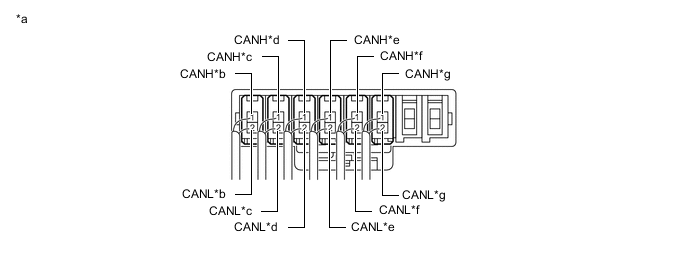
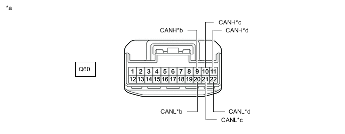
NO. 15 JUNCTION CONNECTOR (for LHD)
-
Check the No. 15 junction connector.
-
Connection diagram

*a Front view of wire harness connector
(to No. 15 Junction Connector)
*b to Front Power Seat Switch LH
(w/ Seat Position Memory System)
*c to No. 3 CAN Junction Connector *d to No. 21 CAN Junction Connector *e to Rear Television Camera Assembly
(w/ Parking Assist Monitor System without Parallel Parking Assist Function)
- - -
Check the connection diagram of the components which are connected to the No. 15 junction connector.
Terminal No. (Symbol) Wiring Color Connected to Q60-8 (CANH) R Front power seat switch LH*1
(for Sub bus 1)
Q60-19 (CANL) B Q60-9 (CANH) LG No. 3 CAN junction connector
(for Sub bus 1)
Q60-20 (CANL) B Q60-10 (CANH) L No. 21 CAN junction connector
(for Sub bus 1)
Q60-21 (CANL) B Q60-11 (CANH) W Rear television camera assembly*2
(for Sub bus 1)
Q60-22 (CANL) B
-
*1: w/ Seat Position Memory System
-
*2: w/ Parking Assist Monitor System without Parallel Parking Assist Function
-
-
-
-
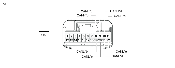
NO. 21 CAN JUNCTION CONNECTOR (for LHD)
-
Check the No. 21 CAN junction connector.
-
Connection diagram
*a Front view of wire harness connector
(to No. 21 CAN Junction Connector)
*b to No. 15 Junction Connector *c to Main Body ECU (Multiplex Network Body ECU) *d to Outer Mirror Control ECU Assembly (for Driver side)
(w/ Seat Position Memory System)
*e to No. 1 Headlight ECU Sub-assembly LH - - -
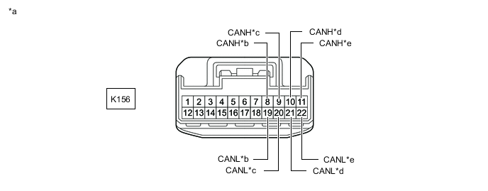
Check the connection diagram of the components which are connected to the No. 21 CAN junction connector.
Terminal No. (Symbol) Wiring Color Connected to K156-8 (CANH) L No. 15 junction connector
(for Sub bus 1)
K156-19 (CANL) B K156-9 (CANH) P Main body ECU (multiplex network body ECU)
(for Sub bus 1)
K156-20 (CANL) B K156-10 (CANH) W Outer mirror control ECU assembly (for driver side)*
(for Sub bus 1)
K156-21 (CANL) B K156-11 (CANH) V No. 1 headlight ECU sub-assembly LH
(for Sub bus 1)
K156-22 (CANL) B
-
*: w/ Seat Position Memory System
-
-
-
-
JUNCTION TERMINAL (for LHD)
-
Check the junction terminal.
-
Connection diagram

*a Front view of wire harness connector
(to Junction Terminal)
*b to No. 3 CAN Junction Connector -
Check the connection diagram of the components which are connected to the junction terminal.
Terminal No. (Symbol) Wiring Color Connected to K106-3 (CANH) P No. 3 CAN junction connector
(for Sub bus 1)
K106-2 (CANL) B
-
-
-
NO. 1 CAN JUNCTION CONNECTOR (for RHD)
-
Check the No. 1 CAN junction connector.
-
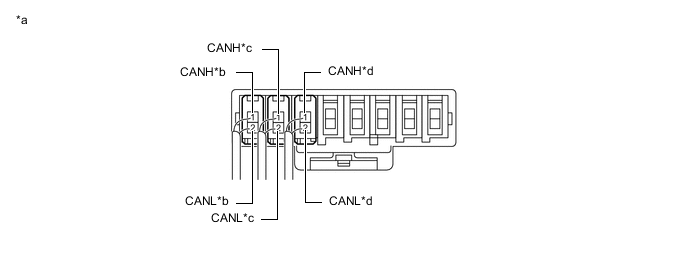
Connection diagram
*a Front view of wire harness connector
(to No. 1 CAN Junction Connector)
*b to No. 2 CAN Junction Connector *c to Combination Meter Assembly *d to Airbag Sensor Assembly *e to Yaw Rate Sensor *f to Skid Control ECU Assembly *g to Steering Sensor - - -
Check the connection diagram of the components which are connected to the No. 1 CAN junction connector.
Terminal No. (Symbol) Wiring Color Connected to K109-1 (CANH) L No. 2 CAN junction connector
(for Bus 2)
K109-11 (CANL) B K109-2 (CANH) LG Combination meter assembly
(for Bus 2)
K109-12 (CANL) B K109-4 (CANH) BE Airbag sensor assembly
(for Bus 2)
K109-14 (CANL) B K109-5 (CANH) G Yaw rate sensor
(for Bus 2)
K109-15 (CANL) B K109-6 (CANH) SB Skid control ECU assembly
(for Bus 2)
K109-16 (CANL) B K109-7 (CANH) P Steering sensor
(for Bus 2)
K109-17 (CANL) B
-
-
-
NO. 2 CAN JUNCTION CONNECTOR (for RHD)
-
Check the No. 2 CAN junction connector.
-
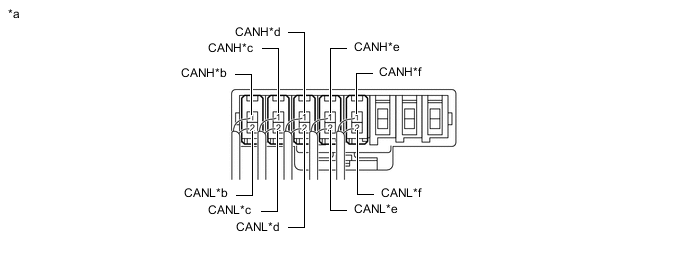
Connection diagram
*a Front view of wire harness connector
(to No. 2 CAN Junction Connector)
*b to No. 1 CAN Junction Connector *c to Main Body ECU (Multiplex Network Body ECU) *d to ECM *e to Central Gateway ECU (Network Gateway ECU) *f to Air Conditioning Amplifier Assembly *g to Hybrid Vehicle Control ECU Assembly *h to Certification ECU (Smart Key ECU Assembly) *i to Stereo Component Equalizer Assembly
(w/ ASC System)
*j to Power Steering ECU Assembly -
Check the connection diagram of the components which are connected to the No. 2 CAN junction connector.
Terminal No. (Symbol) Wiring Color Connected to K110-1 (CANH) L No. 1 CAN junction connector
(for Bus 2)
K110-11 (CANL) B K110-2 (CANH) Y Main body ECU (multiplex network body ECU)
(for Bus 2)
K110-12 (CANL) B K110-3 (CANH) R ECM
(for Bus 2)
K110-13 (CANL) B K110-5 (CANH) BE Central gateway ECU (network gateway ECU)
(for Bus 2)
K110-15 (CANL) B K110-6 (CANH) P Air conditioning amplifier assembly
(for Bus 2)
K110-16 (CANL) B K110-7 (CANH) SB Hybrid vehicle control ECU assembly
(for Bus 2)
K110-17 (CANL) B K110-8 (CANH) W Certification ECU (smart key ECU assembly)
(for Bus 2)
K110-18 (CANL) B K110-9 (CANH) V Stereo component equalizer assembly*
(for Bus 2)
K110-19 (CANL) B K110-10 (CANH) G Power steering ECU assembly
(for Bus 2)
K110-20 (CANL) B
-
*: w/ ASC System
-
-
-
-
NO. 4 CAN JUNCTION CONNECTOR (for RHD)
-
Check the No. 4 CAN junction connector.
-
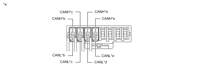
Connection diagram
*a Front view of wire harness connector
(to No. 4 CAN Junction Connector)
*b to Hybrid Vehicle Control ECU Assembly *c to Skid Control ECU Assembly *d to ECM *e to No. 15 Junction Connector *f to Multiplex Tilt and Telescopic ECU
(w/ Power Tilt and Power Telescopic System)
*g to Front Power Seat Switch RH
(w/ Seat Position Memory System)
*h to Outer Mirror Control ECU Assembly (for Driver side)
(w/ Seat Position Memory System)
*i to Junction Terminal - - -
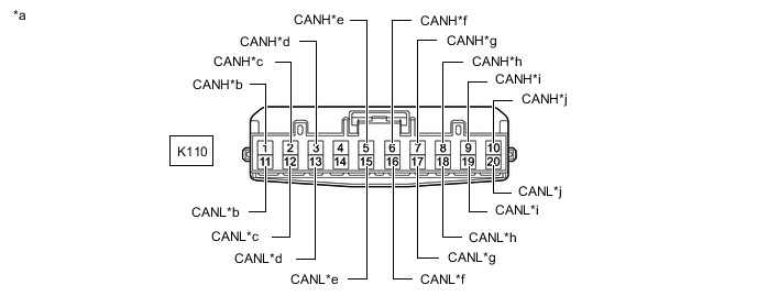
Check the connection diagram of the components which are connected to the No. 4 CAN junction connector.
Terminal No. (Symbol) Wiring Color Connected to K112-1 (CANH) R Hybrid vehicle control ECU assembly
(for Sub bus 15)
K112-12 (CANL) B K112-2 (CANH) W Skid control ECU assembly
(for Sub bus 15)
K112-13 (CANL) B K112-3 (CANH) P ECM
(for Sub bus 15)
K112-14 (CANL) B K112-7 (CANH) LG No. 15 junction connector
(for Sub bus 1)
K112-18 (CANL) B K112-8 (CANH) G Multiplex tilt and telescopic ECU*1
(for Sub bus 1)
K112-19 (CANL) B K112-9 (CANH) R Front power seat switch RH*2
(for Sub bus 1)
K112-20 (CANL) B K112-10 (CANH) W Outer mirror control ECU assembly (for driver side)*2
(for Sub bus 1)
K112-21 (CANL) B K112-11 (CANH) P Junction terminal
(for Sub bus 1)
K112-22 (CANL) B
-
*1: w/ Power Tilt and Power Telescopic System
-
*2: w/ Seat Position Memory System
-
-
-
-
NO. 7 CAN JUNCTION CONNECTOR (for RHD)
-
Check the No. 7 CAN junction connector.
-
Connection diagram
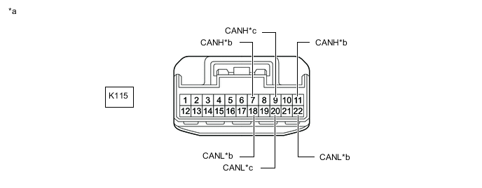
*a Front view of wire harness connector
(to No. 7 CAN Junction Connector)
*b to Central Gateway ECU (Network Gateway ECU) *c to Radio Receiver Assembly
(w/ Navigation System or Audio and Visual System)
- - -
Check the connection diagram of the components which are connected to the No. 7 CAN junction connector.
Terminal No. (Symbol) Wiring Color Connected to K115-7 (CANH) R Central gateway ECU (network gateway ECU)
(for Bus 3)
K115-18 (CANL) B K115-9 (CANH) BE Radio receiver assembly*
(for Bus 3)
K115-20 (CANL) B K115-11 (CANH) V Central gateway ECU (network gateway ECU)
(for Bus 3)
K115-22 (CANL) B
-
*: w/ Navigation System or Audio and Visual System
-
-
-
-
NO. 9 CAN JUNCTION CONNECTOR (for RHD)
-
Check the No. 9 CAN junction connector.
Tech Tips
Connectors that connect to the CAN junction connector can be distinguished by the color of their CAN bus lines. When the connectors have been disconnected from the CAN junction connector, reconnecting the connectors to non-original positions on the CAN junction connector does not affect system performance. However, it is preferred to reconnect the connectors to their original positions to avoid negative effects on the wiring such as tension on the wire harnesses, and to make future maintenance easier.
-
Connection diagram
*a Component with harness connected
(No. 9 CAN Junction Connector)
*b to No. 13 CAN Junction Connector *c to Hybrid Vehicle Control ECU Assembly *d to Blind Spot Monitor Sensor LH
(w/ Blind Spot Monitor System)
-
Check the connection diagram of the components which are connected to the No. 9 CAN junction connector.
Terminal No. (Symbol) Wiring Color Connected to Q63-1 (CANH) BE No. 13 CAN junction connector
(for Bus 5)
Q63-2 (CANL) B Q64-1 (CANH) GR Hybrid vehicle control ECU assembly
(for Bus 5)
Q64-2 (CANL) B Q65-1 (CANH) R Blind spot monitor sensor LH*
(for Bus 5)
Q65-2 (CANL) B
-
*: w/ Blind Spot Monitor System
-
-
-
-
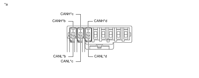
NO. 10 CAN JUNCTION CONNECTOR (for RHD)
-
Check the No. 10 CAN junction connector.
-
Connection diagram
*a Front view of wire harness connector
(to No. 10 CAN Junction Connector)
*b to No. 13 CAN Junction Connector *c to Hybrid Vehicle Control ECU Assembly *d to Blind Spot Monitor Sensor LH
(w/ Blind Spot Monitor System)
-
Check the connection diagram of the components which are connected to the No. 10 CAN junction connector.
Terminal No. (Symbol) Wiring Color Connected to Q68-3 (CANH) BE No. 13 CAN junction connector
(for Bus 5)
Q68-9 (CANL) B Q68-4 (CANH) GR Hybrid vehicle control ECU assembly
(for Bus 5)
Q68-10 (CANL) B Q68-5 (CANH) R Blind spot monitor sensor LH*
(for Bus 5)
Q68-11 (CANL) B
-
*: w/ Blind Spot Monitor System
-
-
-
-
NO. 12 CAN JUNCTION CONNECTOR (for RHD)
-
Check the No. 12 CAN junction connector.
Tech Tips
Connectors that connect to the CAN junction connector can be distinguished by the color of their CAN bus lines. When the connectors have been disconnected from the CAN junction connector, reconnecting the connectors to non-original positions on the CAN junction connector does not affect system performance. However, it is preferred to reconnect the connectors to their original positions to avoid negative effects on the wiring such as tension on the wire harnesses, and to make future maintenance easier.
-
Connection diagram
*a Component with harness connected
(No. 12 CAN Junction Connector)
*b to Central Gateway ECU (Network Gateway ECU) *c to No. 13 CAN Junction Connector *d to Absorber Control ECU
(w/ AVS System)
*e to Driving Support ECU Assembly
(w/ Lexus Safety System +)
- - -
Check the connection diagram of the components which are connected to the No. 12 CAN junction connector.
Terminal No. (Symbol) Wiring Color Connected to K147-1 (CANH) GR Central gateway ECU (network gateway ECU)
(for Bus 5)
K147-2 (CANL) B K148-1 (CANH) LG No. 13 CAN junction connector
(for Bus 5)
K148-2 (CANL) B K149-1 (CANH) SB Absorber control ECU*1
(for Bus 5)
K149-2 (CANL) B K150-1 (CANH) G Driving support ECU assembly*2
(for Bus 5)
K150-2 (CANL) B
-
*1: w/ AVS System
-
*2: w/ Lexus Safety System +
-
-
-
-
NO. 13 CAN JUNCTION CONNECTOR (for RHD)
-
Check the No. 13 CAN junction connector.
Tech Tips
Connectors that connect to the CAN junction connector can be distinguished by the color of their CAN bus lines. When the connectors have been disconnected from the CAN junction connector, reconnecting the connectors to non-original positions on the CAN junction connector does not affect system performance. However, it is preferred to reconnect the connectors to their original positions to avoid negative effects on the wiring such as tension on the wire harnesses, and to make future maintenance easier.
-
Connection diagram
*a Component with harness connected
(No. 13 CAN Junction Connector)
*b to No. 12 CAN Junction Connector *c to Forward Recognition Camera
(w/ Lexus Safety System +)
*d to Millimeter Wave Radar Sensor Assembly
(w/ Lexus Safety System +)
*e to Clearance Warning ECU Assembly
(w/ LEXUS Parking Assist-sensor System)
*f to No. 9 CAN Junction Connector or No. 10 CAN Junction Connector -
Check the connection diagram of the components which are connected to the No. 13 CAN junction connector.
Terminal No. (Symbol) Wiring Color Connected to K151-1 (CANH) LG No. 12 CAN junction connector
(for Bus 5)
K151-2 (CANL) B K152-1 (CANH) R Forward recognition camera*1
(for Bus 5)
K152-2 (CANL) B K153-1 (CANH) L Millimeter wave radar sensor assembly*1
(for Bus 5)
K153-2 (CANL) B K154-1 (CANH) P Clearance warning ECU assembly*2
(for Bus 5)
K154-2 (CANL) B K155-1 (CANH) BE No. 9 CAN junction connector or No. 10 CAN junction connector
(for Bus 5)
K155-2 (CANL) B
-
*1: w/ Lexus Safety System +
-
*2: w/ LEXUS Parking Assist-sensor System
-
-
-
-
NO. 15 JUNCTION CONNECTOR (for RHD)
-
Check the No. 15 junction connector.
-
Connection diagram
*a Front view of wire harness connector
(to No. 15 Junction Connector)
*b to No. 4 CAN Junction Connector *c to No. 21 CAN Junction Connector *d to Rear Television Camera Assembly
(w/ Parking Assist Monitor System without Parallel Parking Assist Function)
-
Check the connection diagram of the components which are connected to the No. 15 junction connector.
Terminal No. (Symbol) Wiring Color Connected to Q60-9 (CANH) LG No. 4 CAN junction connector
(for Sub bus 1)
Q60-20 (CANL) B Q60-10 (CANH) L No. 21 CAN junction connector
(for Sub bus 1)
Q60-21 (CANL) B Q60-11 (CANH) W Rear television camera assembly*
(for Sub bus 1)
Q60-22 (CANL) B
-
*: w/ Parking Assist Monitor System without Parallel Parking Assist Function
-
-
-
-
NO. 21 CAN JUNCTION CONNECTOR (for RHD)
-
Check the No. 21 CAN junction connector.
-
Connection diagram
*a Front view of wire harness connector
(to No. 21 CAN Junction Connector)
*b to No. 15 Junction Connector *c to Main Body ECU (Multiplex Network Body ECU) *d to Outer Mirror Control ECU Assembly (for Front Passenger Side)
(w/ Seat Position Memory System)
*e to No. 1 Headlight ECU Sub-assembly LH - - -
Check the connection diagram of the components which are connected to the No. 21 CAN junction connector.
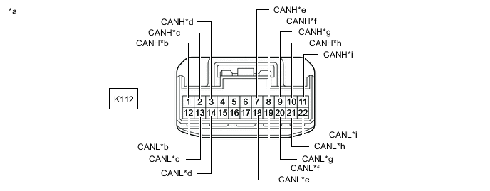
Terminal No. (Symbol) Wiring Color Connected to K156-8 (CANH) L No. 15 junction connector
(for Sub bus 1)
K156-19 (CANL) B K156-9 (CANH) P Main body ECU (multiplex network body ECU)
(for Sub bus 1)
K156-20 (CANL) B K156-10 (CANH) W Outer mirror control ECU assembly (for front passenger side)*
(for Sub bus 1)
K156-21 (CANL) B K156-11 (CANH) V No. 1 headlight ECU sub-assembly LH
(for Sub bus 1)
K156-22 (CANL) B
-
*: w/ Seat Position Memory System
-
-
-
-
JUNCTION TERMINAL (for RHD)
-
Check the junction terminal.
-
Connection diagram

*a Front view of wire harness connector
(to Junction Terminal)
*b to No. 4 CAN Junction Connector -
Check the connection diagram of the components which are connected to the junction terminal.
Terminal No. (Symbol) Wiring Color Connected to K106-3 (CANH) P No. 4 CAN junction connector
(for Sub bus 1)
K106-2 (CANL) B
-
-
-
DLC3
-
Disconnect the cable from the negative (-) auxiliary battery terminal.
-
Measure the resistance according to the value(s) in the table below.
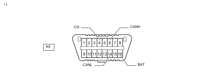
*1 DLC3 - -
-
-
CENTRAL GATEWAY ECU (NETWORK GATEWAY ECU)
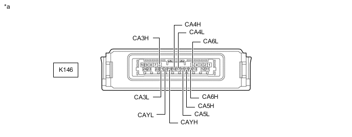
*a Component without harness connected
(Central Gateway ECU (Network Gateway ECU))
- -
-
Disconnect the cable from the negative (-) auxiliary battery terminal.
-
Disconnect the K146 central gateway ECU (network gateway ECU) connector.
-
Measure the resistance according to the value(s) in the table below.
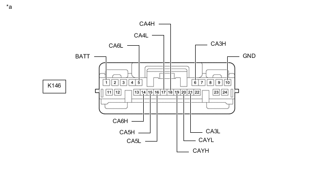
*a Front view of wire harness connector
(to Central Gateway ECU (Network Gateway ECU))
- -
-
-
ECM
Refer to Terminals of ECU.
-
w/ EGR System
-
w/o EGR System
-
Disconnect the cable from the negative (-) auxiliary battery terminal.
-
Disconnect the A78 and F5 ECM connectors.
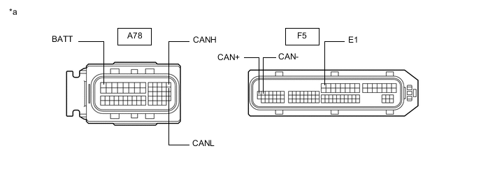
*a Front view of wire harness connector
(to ECM)
- - -
Measure the resistance according to the value(s) in the table below.
-
-
HYBRID VEHICLE CONTROL ECU ASSEMBLY
Refer to Terminals of ECU.
-
Disconnect the cable from the negative (-) auxiliary battery terminal.
-
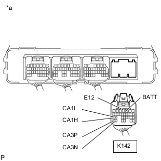
*a Rear view of wire harness connector
(to Hybrid Vehicle Control ECU Assembly)
Disconnect the K142 hybrid vehicle control ECU assembly connector.
-
Measure the resistance according to the value(s) in the table below.
-
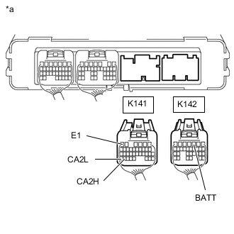
*a Rear view of wire harness connector
(to Hybrid Vehicle Control ECU Assembly)
Disconnect the K141 hybrid vehicle control ECU assembly connector.
-
Measure the resistance according to the value(s) in the table below.
-
-
COMBINATION METER ASSEMBLY
Refer to Terminals of ECU.
-
Disconnect the cable from the negative (-) auxiliary battery terminal.
-
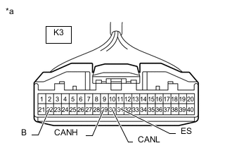
*a Front view of wire harness connector
(to Combination Meter Assembly)
Disconnect the K3 combination meter assembly connector.
-
Measure the resistance according to the value(s) in the table below.
-
-
MAIN BODY ECU (MULTIPLEX NETWORK BODY ECU)
Refer to Terminals of ECU.
-
Disconnect the cable from the negative (-) auxiliary battery terminal.
-
Disconnect the K1 and K2 main body ECU (multiplex network body ECU) connectors.
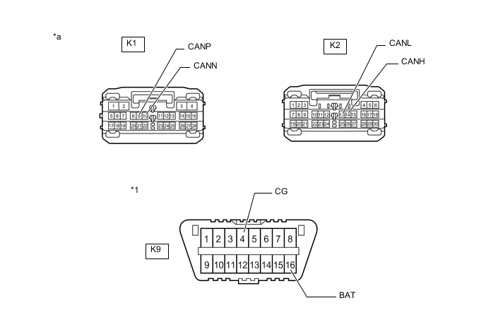
*1 DLC3 - - *a Front view of wire harness connector
(to Main Body ECU (Multiplex Network Body ECU))
- - -
Measure the resistance according to the value(s) in the table below.
-
-
SKID CONTROL ECU ASSEMBLY
Refer to Terminals of ECU.
-
Disconnect the cable from the negative (-) auxiliary battery terminal.
-
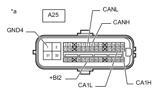
*a Front view of wire harness connector
(to Skid Control ECU Assembly)
Disconnect the A25 skid control ECU assembly connector.
-
Measure the resistance according to the value(s) in the table below.
-
-
STEERING SENSOR
-
Disconnect the cable from the negative (-) auxiliary battery terminal.
-
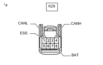
*a Front view of wire harness connector
(to Steering Sensor)
Disconnect the K29 steering sensor connector.
-
Measure the resistance according to the value(s) in the table below.
-
-
YAW RATE SENSOR
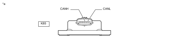
*a Component without harness connected
(Yaw Rate Sensor)
- -
-
Disconnect the cable from the negative (-) auxiliary battery terminal.
-
Disconnect the K85 yaw rate sensor connector.
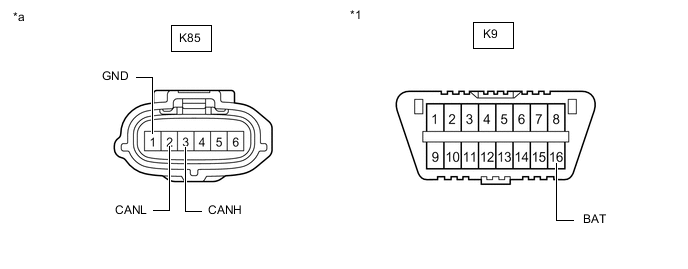
*1 DLC3 - - *a Front view of wire harness connector
(to Yaw Rate Sensor)
- - -
Measure the resistance according to the value(s) in the table below.
-
-
POWER STEERING ECU ASSEMBLY
Refer to Terminals of ECU.
-
Disconnect the cable from the negative (-) auxiliary battery terminal.
-
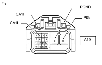
*a Front view of wire harness connector
(to Power Steering ECU Assembly)
Disconnect the A19 power steering ECU assembly connector.
-
Measure the resistance according to the value(s) in the table below.
-
-
AIRBAG SENSOR ASSEMBLY
Refer to Terminals of ECU.
-
Disconnect the cable from the negative (-) auxiliary battery terminal.
-
Disconnect the K51 airbag sensor assembly connector.
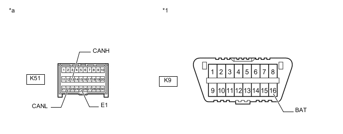
*1 DLC3 - - *a Front view of wire harness connector
(to Airbag Sensor Assembly)
- - -
Measure the resistance according to the value(s) in the table below.
-
-
CERTIFICATION ECU (SMART KEY ECU ASSEMBLY)
Refer to Terminals of ECU.
-
Disconnect the cable from the negative (-) auxiliary battery terminal.
-
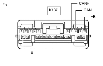
*a Front view of wire harness connector
(to Certification ECU (Smart Key ECU Assembly))
Disconnect the K137 certification ECU (smart key ECU assembly) connector.
-
Measure the resistance according to the value(s) in the table below.
-
-
RADIO RECEIVER ASSEMBLY (w/ Navigation System)
Refer to Terminals of ECU.
-
Disconnect the cable from the negative (-) auxiliary battery terminal.
-
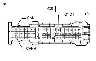
*a Front view of wire harness connector
(to Radio Receiver Assembly)
Disconnect the K58 radio receiver assembly connector.
-
Measure the resistance according to the value(s) in the table below.
-
-
RADIO RECEIVER ASSEMBLY (w/ Audio and Visual System with Parallel Parking Assist Function)
Refer to Terminals of ECU.
-
Disconnect the cable from the negative (-) auxiliary battery terminal.
-
*a Front view of wire harness connector
(to Radio Receiver Assembly)
Disconnect the K58 radio receiver assembly connector.
-
Measure the resistance according to the value(s) in the table below.
-
-
RADIO RECEIVER ASSEMBLY (w/ Audio and Visual System without Parallel Parking Assist Function)
Refer to Terminals of ECU.
-
Disconnect the cable from the negative (-) auxiliary battery terminal.
-
Disconnect the K70 and K72 radio receiver assembly connectors.
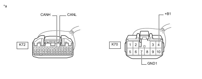
*a Front view of wire harness connector
(to Radio Receiver Assembly)
- - -
Measure the resistance according to the value(s) in the table below.
-
-
AIR CONDITIONING AMPLIFIER ASSEMBLY
Refer to Terminals of ECU.
-
Disconnect the cable from the negative (-) auxiliary battery terminal.
-
Disconnect the K10 and K11 air conditioning amplifier assembly connectors.
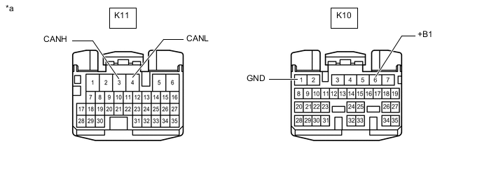
*a Front view of wire harness connector
(to Air Conditioning Amplifier Assembly)
- - -
Measure the resistance according to the value(s) in the table below.
-
-
NO. 1 HEADLIGHT ECU SUB-ASSEMBLY LH
Refer to Terminals of ECU.
-
Disconnect the cable from the negative (-) auxiliary battery terminal.
-
Disconnect the W1 No. 1 headlight ECU sub-assembly LH connector.
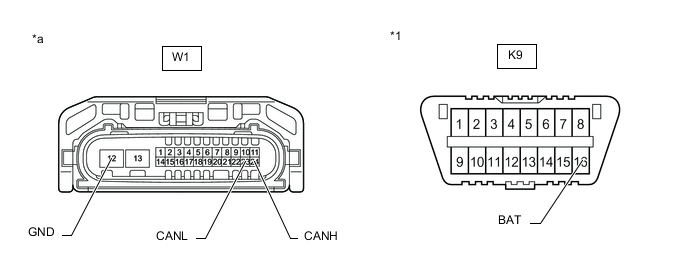
*1 DLC3 - - *a Front view of wire harness connector
(to No. 1 Headlight ECU Sub-assembly LH)
- - -
Measure the resistance according to the value(s) in the table below.
-
-
OUTER MIRROR CONTROL ECU ASSEMBLY (for Driver Side with Seat Position Memory System)
Refer to Terminals of ECU.
-
Disconnect the cable from the negative (-) auxiliary battery terminal.
-
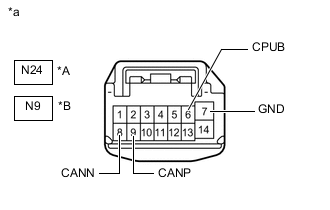
*A for LHD *B for RHD *a Front view of wire harness connector
(to Outer Mirror Control ECU Assembly (for Driver Side))
Disconnect the N9 or N24 outer mirror control ECU assembly (for driver side) connector.
-
Measure the resistance according to the value(s) in the table below.
-
-
OUTER MIRROR CONTROL ECU ASSEMBLY (for Front Passenger Side with Seat Position Memory System)
Refer to Terminals of ECU.
-
Disconnect the cable from the negative (-) auxiliary battery terminal.
-
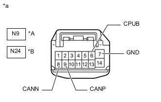
*A for LHD *B for RHD *a Front view of wire harness connector
(to Outer Mirror Control ECU Assembly (for Front Passenger Side))
Disconnect the N9 or N24 outer mirror control ECU assembly (for front passenger side) connector.
-
Measure the resistance according to the value(s) in the table below.
-
-
FRONT POWER SEAT SWITCH LH (for LHD with Seat Position Memory System)
Refer to Terminals of ECU.
-
Disconnect the cable from the negative (-) auxiliary battery terminal.
-
Disconnect the b4 and b12 front power seat switch LH connectors.
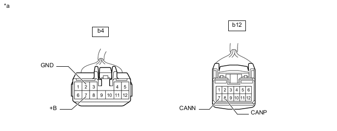
*a Front view of wire harness connector
(to Front Power Seat Switch LH)
- - -
Measure the resistance according to the value(s) in the table below.
-
-
FRONT POWER SEAT SWITCH RH (for RHD with Seat Position Memory System)
Refer to Terminals of ECU.
-
Disconnect the cable from the negative (-) auxiliary battery terminal.
-
Disconnect the a6 and a7 front power seat switch RH connectors.
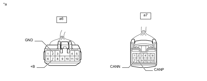
*a Front view of wire harness connector
(to Front Power Seat Switch RH)
- - -
Measure the resistance according to the value(s) in the table below.
-
-
MULTIPLEX TILT AND TELESCOPIC ECU (w/ Power Tilt and Power Telescopic System)
Refer to Terminals of ECU.
-
Disconnect the cable from the negative (-) auxiliary battery terminal.
-
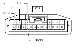
*a Front view of wire harness connector
(to Multiplex Tilt and Telescopic ECU)
Disconnect the K19 multiplex tilt and telescopic ECU connector.
-
Measure the resistance according to the value(s) in the table below.
-
-
BLIND SPOT MONITOR SENSOR LH (w/ Blind Spot Monitor System)
Refer to Terminals of ECU.
-
Disconnect the cable from the negative (-) auxiliary battery terminal.
-
Disconnect the Q50 blind spot monitor sensor LH connector.
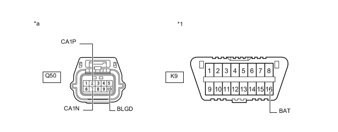
*1 DLC3 - - *a Front view of wire harness connector
(to Blind Spot Monitor Sensor LH)
- - -
Measure the resistance according to the value(s) in the table below.
-
-
CLEARANCE WARNING ECU ASSEMBLY (w/ LEXUS Parking Assist-sensor System)
Refer to Terminals of ECU.
-
Disconnect the cable from the negative (-) auxiliary battery terminal.
-
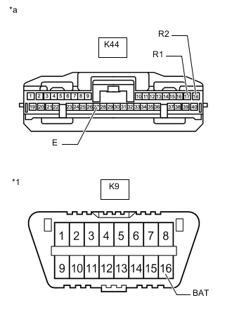
*1 DLC3 *a Front view of wire harness connector
(to Clearance Warning ECU Assembly)
Disconnect the K44 clearance warning ECU assembly connector.
-
Measure the resistance according to the value(s) in the table below.
-
-
ABSORBER CONTROL ECU (w/ AVS System)
Refer to Terminals of ECU.
-
Disconnect the cable from the negative (-) auxiliary battery terminal.
-
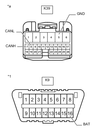
*1 DLC3 *a Front view of wire harness connector
(to Absorber Control ECU)
Disconnect the K39 absorber control ECU connector.
-
Measure the resistance according to the value(s) in the table below.
-
-
STEREO COMPONENT EQUALIZER ASSEMBLY (w/ ASC System)
Refer to Terminals of ECU.
-
Disconnect the cable from the negative (-) auxiliary battery terminal.
-
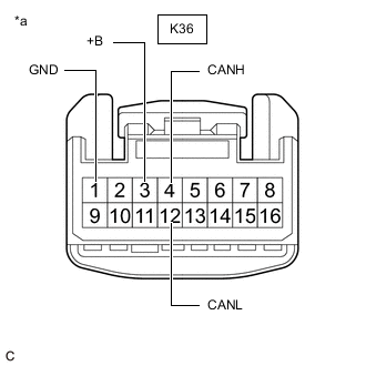
*a Front view of wire harness connector
(to Stereo Component Equalizer Assembly)
Disconnect the K36 stereo component equalizer assembly connector.
-
Measure the resistance according to the value(s) in the table below.
-
-
DRIVING SUPPORT ECU ASSEMBLY (w/ Lexus Safety System +)
Refer to Terminals of ECU.
-
Disconnect the cable from the negative (-) auxiliary battery terminal.
-
Disconnect the M2 driving support ECU assembly connector.
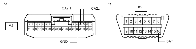
*1 DLC3 - - *a Front view of wire harness connector
(to Driving Support ECU Assembly)
- - -
Measure the resistance according to the value(s) in the table below.
-
-
MILLIMETER WAVE RADAR SENSOR ASSEMBLY (w/ Lexus Safety System +)
Refer to Terminals of ECU.
-
Disconnect the cable from the negative (-) auxiliary battery terminal.
-
Disconnect the B12 millimeter wave radar sensor assembly connector.
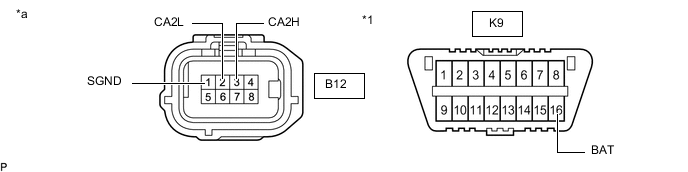
*1 DLC3 - - *a Front view of wire harness connector
(to Millimeter Wave Radar Sensor Assembly)
- - -
Measure the resistance according to the value(s) in the table below.
-
-
FORWARD RECOGNITION CAMERA (w/ Lexus Safety System +)
Refer to Terminals of ECU.
-
Disconnect the cable from the negative (-) auxiliary battery terminal.
-
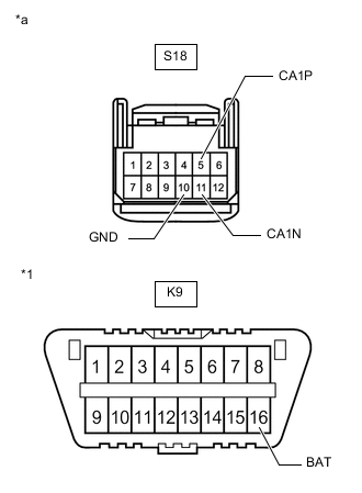
*1 DLC3 *a Front view of wire harness connector
(to Forward Recognition Camera)
Disconnect the S18 forward recognition camera connector.
-
Measure the resistance according to the value(s) in the table below.
-
-
REAR TELEVISION CAMERA ASSEMBLY (w/ Parking Assist Monitor System without Parallel Parking Assist Function)
Refer to Terminals of ECU.
-
Disconnect the cable from the negative (-) auxiliary battery terminal.
-
Disconnect the T2 rear television camera assembly connector.
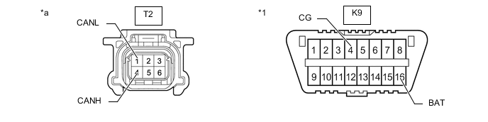
*1 DLC3 - - *a Front view of wire harness connector
(to Rear Television Camera Assembly)
- - -
Measure the resistance according to the value(s) in the table below.
-
-
TELEMATICS TRANSCEIVER (w/ Telematics Transceiver)
Refer to Terminals of ECU.
-
Disconnect the cable from the negative (-) auxiliary battery terminal.
-
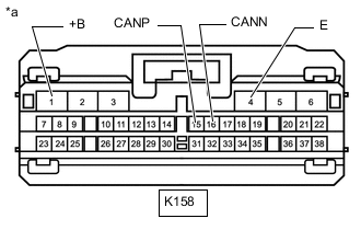
*a Front view of wire harness connector
(to Telematics Transceiver)
Disconnect the K158 telematics transceiver connector.
-
Measure the resistance according to the value(s) in the table below.
-