LIN COMMUNICATION SYSTEM, Diagnostic DTC:B278C
| DTC Code | DTC Name |
|---|---|
| B278C | Lost Communication with Power Source Control |
DESCRIPTION
This DTC is stored when LIN communication between the certification ECU (smart key ECU assembly) and power management control ECU stops for 10 seconds or more.
| DTC No. | Detection Item | DTC Detection Condition | Trouble Area |
|---|---|---|---|
| B278C | Lost Communication with Power Source Control | No communication between the certification ECU (smart key ECU assembly) and power management control ECU for 10 seconds or more. |
|
WIRING DIAGRAM
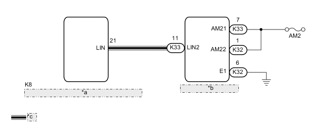
| *a | Certification ECU (Smart Key ECU Assembly) |
| *b | Power Management Control ECU |
| *c | LIN Communication Line |
CAUTION / NOTICE / HINT
Note
-
Inspect the fuses for circuits related to this system before performing the following procedure.
-
If the certification ECU (smart key ECU assembly) or power management control ECU is replaced, refer to Service Bulletin.
-
When using the GTS with the power switch off, connect the GTS to the DLC3 and turn a courtesy light switch on and off at intervals of 1.5 seconds or less until communication between the GTS and the vehicle begins. Then select Model Code "KEY REGIST" under manual mode and enter the following menus: Body Electrical / Entry&Start(CAN). While using the GTS, periodically turn a courtesy light switch on and off at intervals of 1.5 seconds or less to maintain communication between the GTS and the vehicle.
PROCEDURE
-
CHECK HARNESS AND CONNECTOR (CERTIFICATION ECU (SMART KEY ECU ASSEMBLY) - POWER MANAGEMENT CONTROL ECU)
-
Disconnect the K8 certification ECU (smart key ECU assembly) connector.
-
Disconnect the K33 power management control ECU connector.
-
Measure the resistance according to the value(s) in the table below.
Note
Make sure that each ECU is in sleep mode before performing the inspection. To enter sleep mode, turn the power switch from on (IG) to off and wait for 60 seconds or more without operating any switches.
Standard Resistance Tester Connection Condition Specified Condition K33-11 (LIN2) - K8-21 (LIN) Power switch off Below 1 Ω K33-11 (LIN2) - Body ground Power switch off 10 kΩ or higher K8-21 (LIN) - Body ground Power switch off 10 kΩ or higher Result Proceed to OK NG
NG 
REPAIR OR REPLACE HARNESS OR CONNECTOR
OK 
-
-
CHECK HARNESS AND CONNECTOR (POWER MANAGEMENT CONTROL ECU - AUXILIARY BATTERY, BODY GROUND)
-
Disconnect the K32 power management control ECU connector.
-
Measure the voltage according to the value(s) in the table below.
Standard Voltage Tester Connection Condition Specified Condition K33-7 (AM21) - K32-6 (E1) Power switch off 11 to 14 V K32-1 (AM22) - K32-6 (E1) Power switch off 11 to 14 V -
Measure the resistance according to the value(s) in the table below.
Standard Resistance Tester Connection Condition Specified Condition K32-6 (E1) - Body ground Always Below 1 Ω Result Proceed to OK NG
NG
REPAIR OR REPLACE HARNESS OR CONNECTOR
OK
-
-
REPLACE POWER MANAGEMENT CONTROL ECU
-
Replace the power management control ECU.
Result Proceed to NEXT
NEXT
-
-
REGISTER ECU CODE REGISTRATION
-
Register the recognition codes in the ECUs.
Tech Tips
Refer to Service Bulletin.
Result Proceed to NEXT
NEXT
-
-
CHECK DTC OUTPUT
-
Clear the DTCs.
Body Electrical > Entry&Start > Clear DTCs -
Recheck for DTCs.
Body Electrical > Entry&Start > Trouble CodesOK DTC B278C is not output. Result Proceed to OK NG
OK
END (POWER MANAGEMENT CONTROL ECU WAS DEFECTIVE)
NG
REPLACE CERTIFICATION ECU (SMART KEY ECU ASSEMBLY)
-