LIN COMMUNICATION SYSTEM TERMINALS OF ECU
-
CHECK INSTRUMENT PANEL JUNCTION BLOCK ASSEMBLY AND MAIN BODY ECU (MULTIPLEX NETWORK BODY ECU)
-
Disconnect the MB main body ECU (multiplex network body ECU) connector.
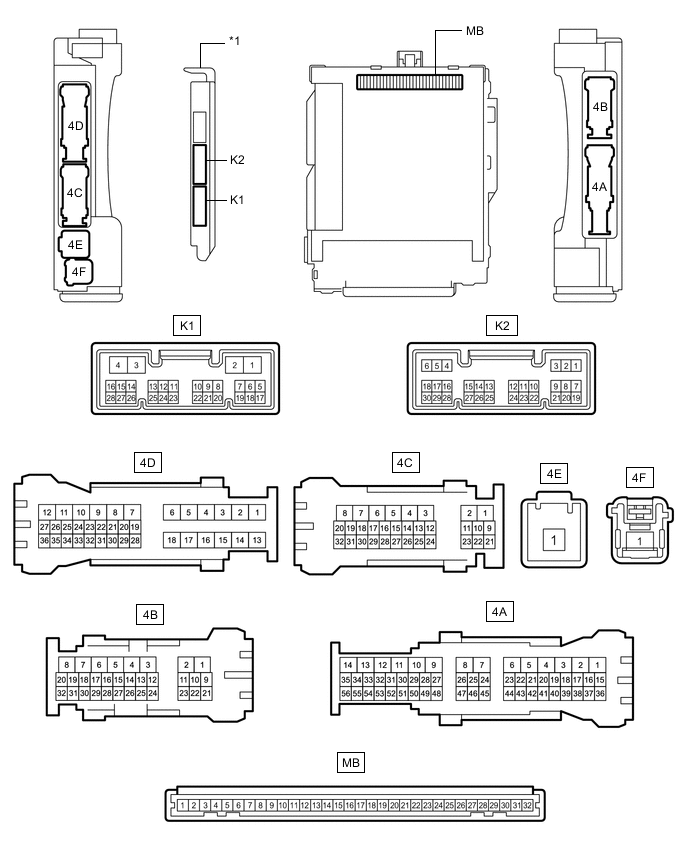
*1 Main Body ECU (Multiplex Network Body ECU) - - -
Measure the voltage and resistance according to the value(s) in the table below.
Tech Tips
Measure the values on the wire harness side with the connectors disconnected.
Tester Connection Wiring Color Terminal Description Condition Specified Condition MB-11 (GND1) - Body ground - Ground Always Below 1 Ω MB-31 (BECU) - Body ground - Auxiliary battery power supply Power switch off 11 to 14 V MB-30 (ACC) - Body ground - ACC power supply Power switch on (ACC) 11 to 14 V MB-30 (ACC) - Body ground - ACC power supply Power switch off Below 1 V MB-32 (IG) - Body ground - IG power supply Power switch on (IG) 11 to 14 V MB-32 (IG) - Body ground - IG power supply Power switch off Below 1 V If the result is not as specified, there may be a malfunction in the wire harness.
-
Reconnect the MB main body ECU (multiplex network body ECU) connector.
-
Check for pulses according to the value(s) in the table below.
Tester Connection Wiring Color Terminal Description Condition Specified Condition 4B-21 - Body ground P - Body ground LIN communication line Power switch on (IG) Pulse generation If the result is not as specified, the main body ECU (multiplex network body ECU) or instrument panel junction block assembly may be malfunctioning.
-
-
CHECK POWER WINDOW REGULATOR MOTOR ASSEMBLY (for Driver Door)
-
Disconnect the N17*1 or N2*2 power window regulator motor assembly (for driver door) connector.
-
*1: for LHD
-
*2: for RHD

*A for LHD *B for RHD -
-
Measure the voltage and resistance according to the value(s) in the table below.
Tech Tips
Measure the values on the wire harness side with the connector disconnected.
for LHD Tester Connection Wiring Color Terminal Description Condition Specified Condition N17-2 (B) - Body ground G - Body ground Auxiliary battery power supply Power switch off 11 to 14 V N17-1 (GND) - Body ground W-B - Body ground Ground Always Below 1 Ω for RHD Tester Connection Wiring Color Terminal Description Condition Specified Condition N2-2 (B) - Body ground Y - Body ground Auxiliary battery power supply Power switch off 11 to 14 V N2-1 (GND) - Body ground W-B - Body ground Ground Always Below 1 Ω If the result is not as specified, there may be a malfunction in the wire harness.
-
Reconnect the N17*1 or N2*2 power window regulator motor assembly (for driver door) connector.
-
*1: for LHD
-
*2: for RHD
-
-
Check for pulses according to the value(s) in the table below.
for LHD Tester Connection Wiring Color Terminal Description Condition Specified Condition N17-9 (LIN) - Body ground P - Body ground LIN communication line Power switch on (IG) Pulse generation for RHD Tester Connection Wiring Color Terminal Description Condition Specified Condition N2-9 (LIN) - Body ground P - Body ground LIN communication line Power switch on (IG) Pulse generation If the result is not as specified, the power window regulator motor assembly (for driver door) may be malfunctioning.
-
-
CHECK POWER WINDOW REGULATOR MOTOR ASSEMBLY (for Front Passenger Door)
-
Disconnect the N2*1 or N17*2 power window regulator motor assembly (for front passenger door) connector.
-
*1: for LHD
-
*2: for RHD

*A for LHD *B for RHD -
-
Measure the voltage and resistance according to the value(s) in the table below.
Tech Tips
Measure the values on the wire harness side with the connector disconnected.
for LHD Tester Connection Wiring Color Terminal Description Condition Specified Condition N2-2 (B) - Body ground Y - Body ground Auxiliary battery power supply Power switch off 11 to 14 V N2-1 (GND) - Body ground W-B - Body ground Ground Always Below 1 Ω for RHD Tester Connection Wiring Color Terminal Description Condition Specified Condition N17-2 (B) - Body ground G - Body ground Auxiliary battery power supply Power switch off 11 to 14 V N17-1 (GND) - Body ground W-B - Body ground Ground Always Below 1 Ω If the result is not as specified, there may be a malfunction in the wire harness.
-
Reconnect the N2*1 or N17*2 power window regulator motor assembly (for front passenger door) connector.
-
*1: for LHD
-
*2: for RHD
-
-
Check for pulses according to the value(s) in the table below.
for LHD Tester Connection Wiring Color Terminal Description Condition Specified Condition N2-9 (LIN) - Body ground P - Body ground LIN communication line Power switch on (IG) Pulse generation for RHD Tester Connection Wiring Color Terminal Description Condition Specified Condition N17-9 (LIN) - Body ground P - Body ground LIN communication line Power switch on (IG) Pulse generation If the result is not as specified, the power window regulator motor assembly (for front passenger door) may be malfunctioning.
-
-
CHECK POWER WINDOW REGULATOR MOTOR ASSEMBLY (for Rear RH Door)
-
Disconnect the O2 power window regulator motor assembly (for rear RH door) connector.

-
Measure the voltage and resistance according to the value(s) in the table below.
Tech Tips
Measure the values on the wire harness side with the connector disconnected.
Tester Connection Wiring Color Terminal Description Condition Specified Condition O2-2 (B) - Body ground R - Body ground Auxiliary battery power supply Power switch off 11 to 14 V O2-1 (GND) - Body ground W-B - Body ground Ground Always Below 1 Ω If the result is not as specified, there may be a malfunction in the wire harness.
-
Reconnect the O2 power window regulator motor assembly (for rear RH door) connector.
-
Check for pulses according to the value(s) in the table below.
Tester Connection Wiring Color Terminal Description Condition Specified Condition O2-9 (LIN) - Body ground P - Body ground LIN communication line Power switch on (IG) Pulse generation If the result is not as specified, the power window regulator motor assembly (for rear RH door) may be malfunctioning.
-
-
CHECK POWER WINDOW REGULATOR MOTOR ASSEMBLY (for Rear LH Door)
-
Disconnect the O7 power window regulator motor assembly (for rear LH door) connector.

-
Measure the voltage and resistance according to the value(s) in the table below.
Tech Tips
Measure the values on the wire harness side with the connector disconnected.
Tester Connection Wiring Color Terminal Description Condition Specified Condition O7-2 (B) - Body ground B - Body ground Auxiliary battery power supply Power switch off 11 to 14 V O7-1 (GND) - Body ground W-B - Body ground Ground Always Below 1 Ω If the result is not as specified, there may be a malfunction in the wire harness.
-
Reconnect the O7 power window regulator motor assembly (for rear LH door) connector.
-
Check for pulses according to the value(s) in the table below.
Tester Connection Wiring Color Terminal Description Condition Specified Condition O7-9 (LIN) - Body ground P - Body ground LIN communication line Power switch on (IG) Pulse generation If the result is not as specified, the power window regulator motor assembly (for rear LH door) may be malfunctioning.
-
-
CHECK MULTIPLEX NETWORK MASTER SWITCH ASSEMBLY (w/o Seat Position Memory System)
-
Disconnect the N27*1 or N12*2 multiplex network master switch assembly connector.
-
*1: for LHD
-
*2: for RHD

*A for LHD *B for RHD -
-
Measure the voltage and resistance according to the value(s) in the table below.
Tech Tips
Measure the values on the wire harness side with the connector disconnected.
for LHD Tester Connection Wiring Color Terminal Description Condition Specified Condition N27-21 (B) - Body ground LG - Body ground Auxiliary battery power supply Power switch off 11 to 14 V N27-17 (GND) - Body ground W-B - Body ground Ground Always Below 1 Ω for RHD Tester Connection Wiring Color Terminal Description Condition Specified Condition N12-21 (B) - Body ground LG - Body ground Auxiliary battery power supply Power switch off 11 to 14 V N12-17 (GND) - Body ground W-B - Body ground Ground Always Below 1 Ω If the result is not as specified, there may be a malfunction in the wire harness.
-
Reconnect the N27*1 or N12*2 multiplex network master switch assembly connector.
-
*1: for LHD
-
*2: for RHD
-
-
Check for pulses according to the value(s) in the table below.
for LHD Tester Connection Wiring Color Terminal Description Condition Specified Condition N27-7 (LIN1) - Body ground P - Body ground LIN communication line Power switch on (IG) Pulse generation for RHD Tester Connection Wiring Color Terminal Description Condition Specified Condition N12-7 (LIN1) - Body ground P - Body ground LIN communication line Power switch on (IG) Pulse generation If the result is not as specified, the multiplex network master switch assembly may be malfunctioning.
-
-
CHECK MULTIPLEX NETWORK MASTER SWITCH ASSEMBLY (w/ Seat Position Memory System)
-
Disconnect the N18*1 or N3*2 multiplex network master switch assembly connector.
-
*1: for LHD
-
*2: for RHD

*A for LHD *B for RHD -
-
Measure the voltage and resistance according to the value(s) in the table below.
Tech Tips
Measure the values on the wire harness side with the connector disconnected.
for LHD Tester Connection Wiring Color Terminal Description Condition Specified Condition N18-11 (B) - Body ground LG - Body ground Auxiliary battery power supply Power switch off 11 to 14 V N18-12 (GND) - Body ground W-B - Body ground Ground Always Below 1 Ω for RHD Tester Connection Wiring Color Terminal Description Condition Specified Condition N3-11 (B) - Body ground LG - Body ground Auxiliary battery power supply Power switch off 11 to 14 V N3-12 (GND) - Body ground W-B - Body ground Ground Always Below 1 Ω If the result is not as specified, there may be a malfunction in the wire harness.
-
Reconnect the N18*1 or N3*2 multiplex network master switch assembly connector.
-
*1: for LHD
-
*2: for RHD
-
-
Check for pulses according to the value(s) in the table below.
for LHD Tester Connection Wiring Color Terminal Description Condition Specified Condition N18-17 (LIN1) - Body ground P - Body ground LIN communication line Power switch on (IG) Pulse generation for RHD Tester Connection Wiring Color Terminal Description Condition Specified Condition N3-17 (LIN1) - Body ground P - Body ground LIN communication line Power switch on (IG) Pulse generation If the result is not as specified, the multiplex network master switch assembly may be malfunctioning.
-
-
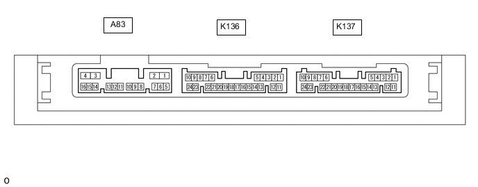
CHECK CERTIFICATION ECU (SMART KEY ECU ASSEMBLY)
-
Disconnect the K8 certification ECU (smart key ECU assembly) connector.
-
Measure the voltage and resistance according to the value(s) in the table below.
Tech Tips
Measure the values on the wire harness side with the connector disconnected.
Tester Connection Wiring Color Terminal Description Condition Specified Condition K137-11 (E) - Body ground BR - Body ground Ground Always Below 1 Ω K137-10 (+B) - Body ground G - Body ground Auxiliary battery power supply Power switch off 11 to 14 V If the result is not as specified, there may be a malfunction in the wire harness.
-
Reconnect the K8 certification ECU (smart key ECU assembly) connector.
-
Check for pulses according to the value(s) in the table below.
Tester Connection Wiring Color Terminal Description Condition Specified Condition K137-9 (LIN) - Body ground V - Body ground LIN communication line Power switch on (IG) Pulse generation If the result is not as specified, the certification ECU (smart key ECU assembly) may be malfunctioning.
-
-
CHECK STEERING LOCK ECU (STEERING LOCK ACTUATOR ASSEMBLY)
-
Disconnect the K28 steering lock ECU (steering lock actuator assembly) connector.

-
Measure the resistance and voltage according to the value(s) in the table below.
Tester Connection Wiring Color Terminal Description Condition Specified Condition K28-1 (GND) - Body ground W-B Body ground Ground Always Below 1 Ω K28-7 (B) - Body ground G - Body ground Auxiliary battery power supply Power switch off 11 to 14 V If the result is not as specified, there may be a malfunction on the wire harness side.
-
Reconnect the K28 steering lock ECU (steering lock actuator assembly) connector.
-
Check for pulses according to the value(s) in the table below.
Tester Connection Wiring Color Terminal Description Condition Specified Condition K28-5 (LIN) - Body ground V - Body ground LIN communication line Power switch on (IG) Pulse generation If the result is not as specified, the steering lock ECU (steering lock actuator assembly) may be malfunctioning.
-
-
CHECK ID CODE BOX (IMMOBILISER CODE ECU)
-
Disconnect the K83 ID code box (immobiliser code ECU) connector.

-
Measure the voltage and resistance according to the value(s) in the table below.
Tech Tips
Measure the values on the wire harness side with the connector disconnected.
Tester Connection Wiring Color Terminal Description Condition Specified Condition K83-5 (GND) - Body ground BR - Body ground Ground Always Below 1 Ω K83-1 (+B) - Body ground G - Body ground Auxiliary battery power supply Power switch off 11 to 14 V If the result is not as specified, there may be a malfunction in the wire harness.
-
Reconnect the K83 ID code box (immobiliser code ECU) connector.
-
Check for pulses according to the value(s) in the table below.
Tester Connection Wiring Color Terminal Description Condition Specified Condition K83-2 (LIN1) - Body ground V - Body ground LIN communication line Power switch on (IG) Pulse generation If the result is not as specified, the ID code box (immobiliser code ECU) may be malfunctioning.
-
-
CHECK SLIDING ROOF ECU (SLIDING ROOF DRIVE GEAR SUB-ASSEMBLY) (w/ Sliding Roof System)
-
Disconnect the S5 sliding roof ECU (sliding roof drive gear sub-assembly) connector.

-
Measure the resistance and voltage according to the value(s) in the table below.
Tech Tips
Measure the values on the wire harness side with the connector disconnected.
Tester Connection Wiring Color Terminal Description Condition Specified Condition S5-8 (B) - Body ground V - Body ground Auxiliary battery power supply Power switch off 11 to 14 V S5-12 (E) - Body ground W-B - Body ground Ground Always Below 1 Ω If the result is not as specified, there may be a malfunction in the wire harness.
-
Reconnect the S5 sliding roof ECU (sliding roof drive gear sub-assembly) connector.
-
Measure the voltage according to the value(s) in the table below.
Tester Connection Wiring Color Terminal Description Condition Specified Condition S5-11 (MPX1) - Body ground P - Body ground LIN communication line Power switch on (IG) Pulse generation If the result is not as specified, the sliding roof ECU (sliding roof drive gear sub-assembly) may be malfunctioning.
-
-
CHECK DOUBLE LOCK DOOR CONTROL RELAY ASSEMBLY (w/ Double Locking System)
-
Disconnect the K138 double lock door control relay assembly connector.

-
Measure the resistance and voltage according to the value(s) in the table below.
Tech Tips
Measure the values on the wire harness side with the connector disconnected.
Tester Connection Wiring Color Terminal Description Condition Specified Condition K138-12 (+B) - Body ground W - Body ground Auxiliary battery power supply Power switch off 11 to 14 V K138-11 (CPUB) - Body ground LG - Body ground Auxiliary battery power supply Power switch off 11 to 14 V K138-7 (GND) - Body ground W-B - Body ground Ground Always Below 1 Ω If the result is not as specified, there may be a malfunction in the wire harness.
-
Reconnect the K138 double lock door control relay assembly connector.
-
Check for pulses according to the value(s) in the table below.
Tester Connection Wiring Color Terminal Description Condition Specified Condition K138-9 (LIN) - Body ground P - Body ground LIN communication line Double lock unset Pulse generation If the result is not as specified, the double lock door control relay assembly may be malfunctioning.
-