MAIN BODY ECU REMOVAL
PROCEDURE
-
PRECAUTION
Note
If the main body ECU (multiplex network body ECU) is replaced, refer to Service Bulletin.
-
REMOVE NO. 1 INSTRUMENT PANEL UNDER COVER SUB-ASSEMBLY (for LHD)
-
DISCONNECT HOOD LOCK CONTROL LEVER SUB-ASSEMBLY (for LHD)
-
REMOVE LOWER INSTRUMENT PANEL FINISH PANEL SUB-ASSEMBLY (for LHD)
-
REMOVE LOWER NO. 2 INSTRUMENT PANEL AIRBAG ASSEMBLY (for RHD)
-
REMOVE INSTRUMENT PANEL FINISH PANEL END LH (for RHD)
-
REMOVE FRONT NO. 1 CONSOLE BOX INSERT (for RHD)
-
REMOVE GLOVE COMPARTMENT DOOR ASSEMBLY (for RHD)
-
REMOVE INSTRUMENT PANEL JUNCTION BLOCK ASSEMBLY WITH MAIN BODY ECU (for LHD)
-
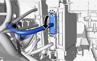
Disconnect each connector.
-
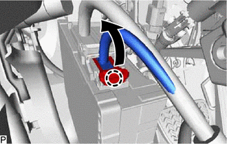
Disengage the claw and disconnect the connector as shown in the illustration.
-
Disengage the claw and disconnect the connector as shown in the illustration.
-
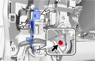

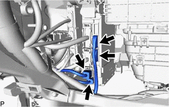
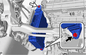
Bolt 
Nut Remove the bolt and 2 nuts, and disconnect the wiring harness clamp bracket.
-
Pull out the instrument panel junction block assembly with main body ECU.
-
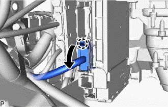
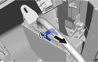
Disengage the claw and disconnect the connector as shown in the illustration.
-
w/ Connector Lock:
-
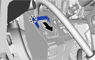
Disengage the claw and release the connector lock as shown in the illustration.
-
-
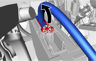
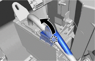
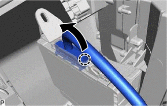
Disengage the claw and disconnect the connector as shown in the illustration and remove the instrument panel junction block assembly with main body ECU.
-
-
REMOVE INSTRUMENT PANEL JUNCTION BLOCK ASSEMBLY WITH MAIN BODY ECU (for RHD)
-
Disconnect each connector.
-
Disengage the claw and disconnect the connector as shown in the illustration.
-
Disengage the claw and disconnect the connector as shown in the illustration.
-
Bolt Nut Remove the bolt and nut, and pull out the instrument panel junction block assembly with main body ECU.
-
Disengage the claw and disconnect the connector as shown in the illustration.
-
w/ Connector Lock:
-
Disengage the claw and release the connector lock as shown in the illustration.
-
-
Disengage the claw and disconnect the connector as shown in the illustration and remove the instrument panel junction block assembly with main body ECU.
-
-
REMOVE MAIN BODY ECU (MULTIPLEX NETWORK BODY ECU)
-
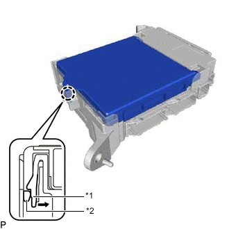
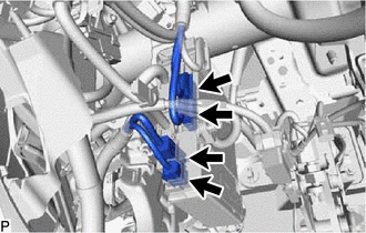
*1 Instrument Panel Junction Block Assembly *2 Main Body ECU (Multiplex Network Body ECU) Press the claw of the instrument panel junction block assembly as shown in the illustration to release the lock.
-
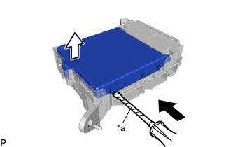
*a Protective Tape With the instrument panel junction block assembly lock released, insert a screwdriver with its tip wrapped with protective tape horizontally between the main body ECU (multiplex network body ECU) and instrument panel junction block assembly.
Note
-
Use a screwdriver with a diameter between 5.0 mm (0.197 in.) and 6.3 mm (0.248 in.) and a length of approximately 90 mm (3.54 in.).
-
Do not insert the screwdriver under the connector socket of the main body ECU (multiplex network body ECU).
-
-
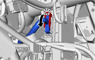
Using the screwdriver, carefully raise the main body ECU (multiplex network body ECU) to the position where the connector becomes disconnected.
Note
Do not twist the screwdriver to raise the main body ECU (multiplex network body ECU).
-
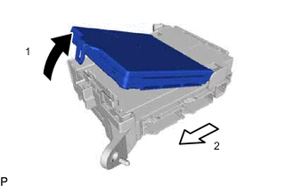
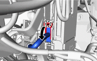
Raise the main body ECU (multiplex network body ECU) as shown by the arrow (1), and then pull it out as shown by the arrow (2) in the illustration.
Note
Do not touch the main body ECU (multiplex network body ECU) connector.
-