BLIND SPOT MONITOR SYSTEM Buzzer does not Sound
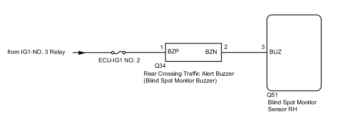
WIRING DIAGRAM
CAUTION / NOTICE / HINT
Note
-
When checking for DTCs, make sure that the blind spot monitor system is turned on.
-
Inspect the fuses for circuits related to this system before performing the following inspection procedure.
PROCEDURE
-
CHECK REAR CROSSING TRAFFIC ALEAT BUZZER (BLIND SPOT MONITOR BUZZER)
-
Check that the Rear Crossing Traffic Alert Buzzer (Blind Spot Monitor Buzzer) sounds when the initial check is performed.
OK Rear Crossing Traffic Alert Buzzer (Blind Spot Monitor Buzzer) sounds Result Proceed to OK NG
OK 
REPLACE BLIND SPOT MONITOR SENSOR RH Click here
NG 
-
-
CHECK DTC
-
Turn the power switch off.
-
Turn the power switch on (IG).
-
Recheck for DTCs and check if the same DTC is output again.
Body Electrical > Blind Spot Monitor Slave > Trouble CodesOK No DTCs are output. Result Proceed to OK NG
NG
GO TO DTC CHART Click here
OK
-
-
CHECK HARNESS AND CONNECTOR (REAR CROSSING TRAFFIC ALERT BUZZER (BLIND SPOT MONITOR BUZZER) - BLIND SPOT MONITOR SENSOR RH)
-
Disconnect the Q34 Rear Crossing Traffic Alert Buzzer (Blind Spot Monitor Buzzer) connector.
-
Measure the voltage according to the value(s) in the table below.
Standard Voltage Tester Connection Switch Condition Specified Condition Q34-1 (BZP) - Body ground Power switch on (IG) 11 to 14 V Q34-2 (BZN) - Body ground Below 1 V Q34-2 (BZN) - Q34-1 (BZP) Below 1 V Result Proceed to OK NG
NG
REPAIR OR REPLACE HARNESS OR CONNECTOR
OK
-
-
CHECK HARNESS AND CONNECTOR (REAR CROSSING TRAFFIC ALERT BUZZER (BLIND SPOT MONITOR BUZZER) - BLIND SPOT MONITOR SENSOR RH AND AUXILIARY BATTERY)
-
Disconnect the Q34 Rear Crossing Traffic Alert Buzzer (Blind Spot Monitor Buzzer) connector.
-
Disconnect the Q51 blind spot monitor sensor RH connector.
-
Measure the resistance according to the value(s) in the table below.
Standard Resistance Tester Connection Condition Specified Condition Q34-2 (BZN) - Q51-3 (BUZ) Always Below 1 Ω Q34-2 (BZN) or Q51-3 (BUZ) - Body ground Always 10 kΩ or higher -
Measure the voltage according to the value(s) in the table below.
Standard Voltage Tester Connection Switch Condition Specified Condition Q34-2 (BZN) or Q51-3 (BUZ) - Body ground Power switch on (IG) Below 1 V Q34-1 (BZP) - Body ground Power switch on (IG) 11 to 14 V Q34-1 (BZP) - Body ground Power switch on (IG) Below 1 V Result Proceed to OK NG
OK
REPLACE BLIND SPOT MONITOR BUZZER Click here
NG
REPAIR OR REPLACE HARNESS OR CONNECTOR
-