BLIND SPOT MONITOR SYSTEM DIAGNOSIS SYSTEM
-
DESCRIPTION
-
Blind spot monitor data and Diagnostic Trouble Codes (DTCs) can be read from the Data Link Connector 3 (DLC3) of the vehicle. When the system seems to be malfunctioning, use the GTS to check for malfunctions and to repair it.
-
-
CHECK DLC3
-
Check the DLC3.
-
-
DIAGNOSIS FUNCTION
-
The blind spot monitor system displays an error message on the multi-information display to inform the driver that the system is unavailable either temporarily or due to a malfunction.
-
When the system is unavailable temporarily:
Multi-information display displays "BSM not available".
-
When the system is unavailable due to a malfunction:
Multi-information display displays "Check BSM System".
-
-
If the RCTA function is not operating correctly, the blind spot monitor system displays the RCTA icon on the multi-display assembly to inform the driver of the malfunction
Malfunctioning Item Detection Condition Malfunction Indication Suspected Area System Malfunction Indication
-
Blind spot monitor sensor LH is malfunctioning
-
Blind spot monitor sensor RH is malfunctioning
○ Check for DTCs Click here
Communication Malfunction Indication CAN communication stop between blind spot monitor sensor LH and rear television camera assembly ○ Go to CAN communication system
-
Malfunction Indication
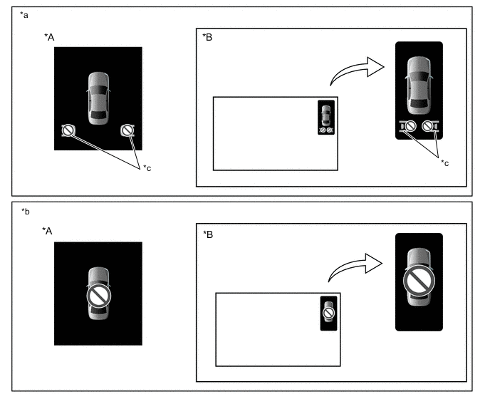
*A for 10.3 Inch Display *B for 7 Inch Display w/ Parking Assist Monitor System (w/o Parallel Parking Assist Function) *a System Malfunction Indication *b Communication Malfunction Indication *c RCTA Icon - -
-
-
-
ABNORMALITY HISTORY
Tech Tips
The abnormality history for a blind spot monitor sensor can be displayed or cleared.
-
Check abnormality history
-
Connect the GTS to the DLC3.
-
Turn the power switch on (IG).
-
Turn the GTS on.
-
Turn the blind spot monitor main switch (warning canceling switch assembly) on.
-
Enter the following menus: Body Electrical / Blind Spot Monitor Master or Blind Spot Monitor Slave / Utility / BSM Master Abnormal History or BSM Slave Abnormal History.
Body Electrical > Blind Spot Monitor Master > UtilityTester Display BSM Master Abnormal History
Body Electrical > Blind Spot Monitor Slave > UtilityTester Display BSM Slave Abnormal History -
Check the results displayed for the abnormality history check.
Tech Tips
-
If "Yes" is displayed, check the suspected area column for each item.
-
Abnormality history is stored only for the blind spot monitor sensor for which an abnormality has been detected.
-
If "No" is displayed, refer to Problem Symptoms Table.
Abnormality History Table Tester Display Item Explanation Suspected Area History of Module Blockage History of blind spot monitor sensor detection problems due to snow, rain, etc. on the bumper
-
Check if a bumper compatible with the blind spot monitor (such as an original equipment bumper) is installed
-
Check if any foreign matter is attached to the bumper
-
Check if any foreign matter is present between the bumper and sensors
History of Low Voltage History of low supply auxiliary battery voltage from auxiliary battery to the blind spot monitor sensor Power Source Circuit
History of High Voltage History of high supply auxiliary battery voltage from auxiliary battery to the blind spot monitor sensor History of Low Temperature History of low temperature for the blind spot monitor sensor
-
Check the outside temperature
-
Check if any foreign matter is attached to the blind spot monitor sensors and their surrounding areas
History of High Temperature History of high temperature for the blind spot monitor sensor -
-
-
Clearing abnormality history
-
Connect the GTS to the DLC3.
-
Turn the power switch on (IG).
-
Turn the GTS on.
-
Turn the blind spot monitor main switch (warning canceling switch assembly) on.
-
Enter the following menus: Body Electrical / Blind Spot Monitor Master or Blind Spot Monitor Slave / Utility / BSM Master Abnormal History or BSM Slave Abnormal History.
Body Electrical > Blind Spot Monitor Master > UtilityTester Display BSM Master Abnormal History
Body Electrical > Blind Spot Monitor Slave > UtilityTester Display BSM Slave Abnormal History -
Clear the abnormal history.
-
-